Screw type vacuum pump

Inactive Publication Date: 2007-05-08
TAIKO KIKAI INDS
View PDF8 Cites 22 Cited by
  • Summary
  • Abstract
  • Description
  • Claims
  • Application Information

AI Technical Summary

Benefits of technology

[0011]In thus configured pump, a gas introduced in the pump casing is compressed at a first stage by the first type of helical teeth, in which a part of the gas is discharged into the bypass conduit via a check valve when the pressure of the gas becomes more than a predetermined value (for example, an atmospheric pressure). The remaining gas is further compressed at a second stage by the second type helical teeth, in which a part of the gas is discharged into the bypass conduit via a check valve when the pressure of the gas becomes more than a predetermined value as well as the first stage. The remaining gas is further compressed at

Problems solved by technology

However, the conventional vacuum pump 61, as illustrated in a characteristic curve of FIG. 6, requires a comparatively larger power (shat driving power La), which disadvantageously increases a delivery gas temperature more than 200° C. In FIG. 6, a lower graph shows a shaft driving power (kW) while an upper graph shows a discharge gas flow rate (1/minute).
Moreover, the gas compressed via the two stages tends to cause a consider

Method used


Image

  • Screw type vacuum pump
  • Screw type vacuum pump
  • Screw type vacuum pump

Examples


Example

BEST MODE EMBODYING THE INVENTION

[0022]Referring to the accompanied drawings, an embodiment of the present invention will be discussed.

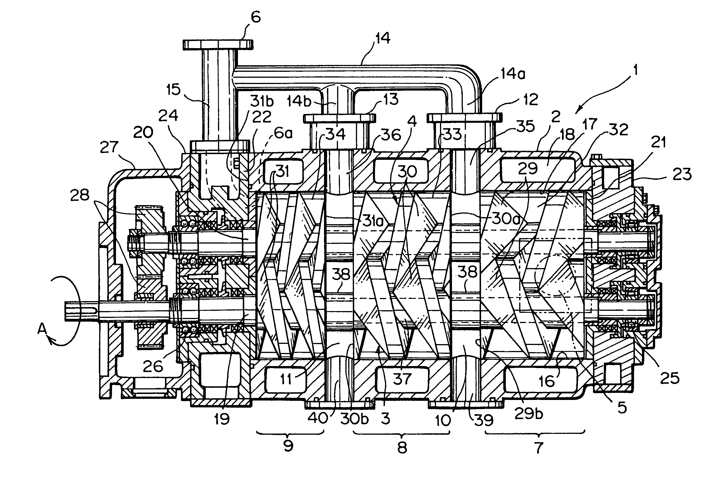
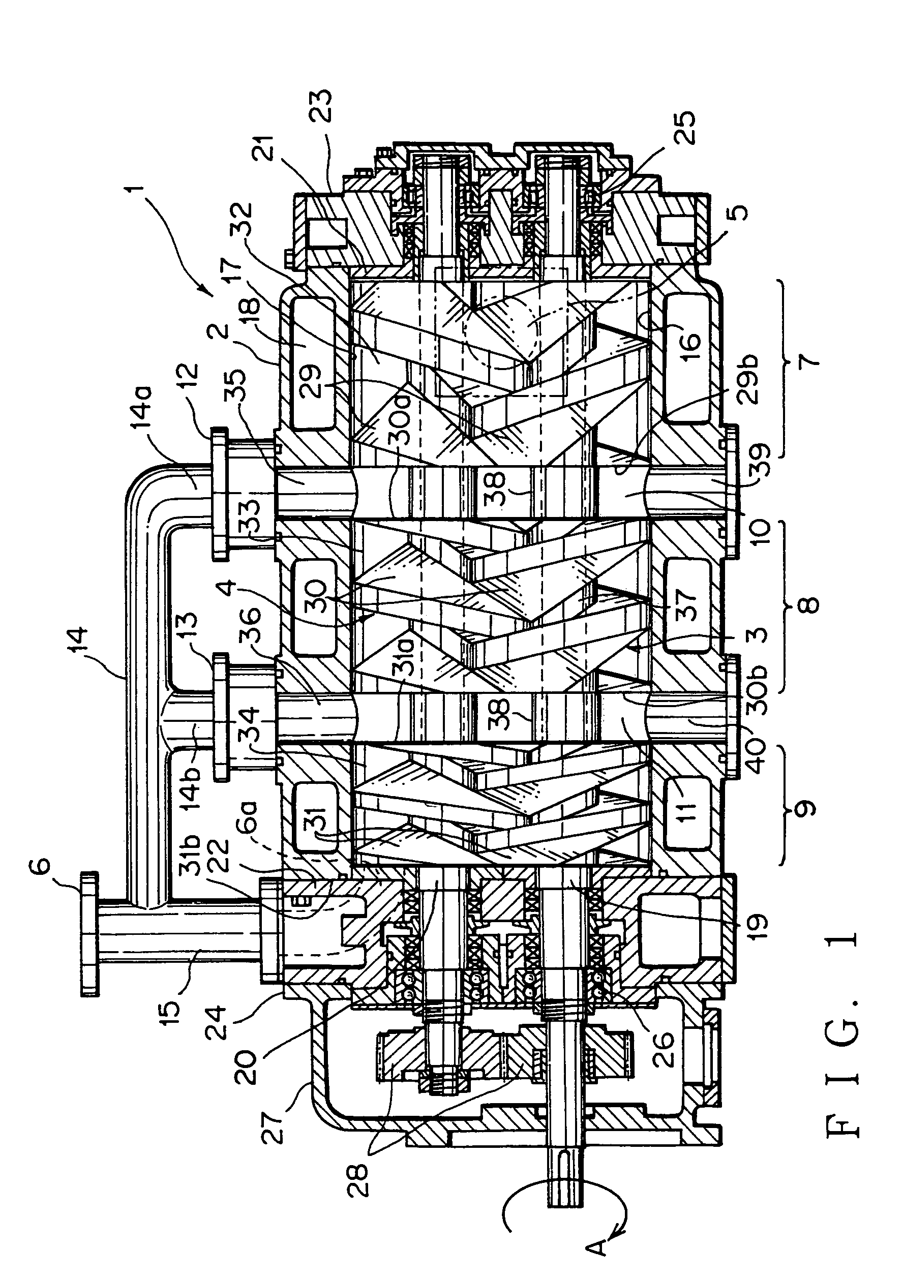
[0023]FIG. 1 shows an embodiment of a screw vacuum pump, more definitely of a screw-type dry vacuum pump, according to the present invention.

[0024]The vacuum pump 1 has a metal casing 2 in which there are a pair of screw rotors 3, 4. The screw rotor 3 has a clockwise helical screw while the screw rotor 4 has a counterclockwise helical screw such that the screws rotatively engage with each other. Each of the screws of the rotors 3, 4 has three types of pitches serially in its longitudinal direction. This provides first to third compression stages 7, 8, and 9 between a suction port 5 and a discharge outlet 6 within the casing 2. More specifically, an intermediate space 10 defined between the first stage 7 and the second stage 8 communicates via a check valve 12 with a pipe conduit (bypass pipe) 14 located outside the casing. Furthermore, an intermediat...


PUM


Abstract

A screw vacuum pump which allows reduced power, lower inside gas temperature, and reduced discharging time. The pump has a pair of screw rotors rotatively engaged with each other in a pump casing to discharge a gas along a longitudinal direction of the pump. Each rotor has three types of helical teeth serially located in a longitudinal direction of the rotor and different from each other in theoretical displacement volume. A bypass conduit communicating with a delivery side of the pump is connected via a first check valve to a first intermediate space defined between the first helical teeth and the second helical teeth and via a second check valve to a second intermediate space defined between the second helical teeth and the third helical teeth. The gas is compressed at the third stage to half the first stage volume before a discharge port opens.

Description

FIELD OF THE INVENTION[0001]The present invention relates to a screw vacuum pump having a pair of multiple-stage-screw rotors to compress a gas sequentially with a plurality of steps.BACKGROUND OF THE INVENTION[0002]Recently, it has been desired that a vacuum pump requires a smaller energy (electrical power) to reduce CO2 emission in view of an environmental control. In Europe (EC), a chemical gas vacuum pump needs to have a discharge side temperature not more than 135° C. according to a safety standard. The temperature corresponds to a temperature grade T4 of the standard, in which acetaldehyde, trimethylamine, ethyl-methyl-ether, diethyl-ether, etc. are listed. These materials need to have a gas temperature not more than 135° C. at an outer surface thereof.[0003]A conventional screw vacuum pump is disclosed in Japanese Patent Application Laid-open No. 63-36085, which is a single-stage pump having a pair of screw rotors. Another conventional screw vacuum pump is shown in FIG. 5, wh...

Claims


Application Information

Patent Timeline
IPC IPC(8): F04B25/00F04C18/08F04C18/16F04C23/00F04C25/02F04C28/02F04C28/26
CPCF04C18/084F04C18/16F04C23/001F04C28/26F04C2220/10
Inventor YOSHIMURA, MASASHI
Owner TAIKO KIKAI INDS
Why Eureka
Try Eureka