Power supply system for vehicle

a technology for power supply systems and vehicles, applied in hybrid vehicles, electric generator control, instruments, etc., can solve the problems of increasing the cost of installation of spare systems and the inability to generate electric power

Inactive Publication Date: 2007-05-08
HITACHI LTD
View PDF18 Cites 34 Cited by
  • Summary
  • Abstract
  • Description
  • Claims
  • Application Information

AI Technical Summary

Benefits of technology

[0005]The object of the present invention is to provide a power supply system for vehicle which is capable of generating electric power when a circuit malfunction occurs, thereby making it possible for the driver to drive the vehicle to a repair shop.
[0018](5) In the above item 1, when said field coil is not energized, it is preferable that said control means reduces the gear ratio of the transmission that changes the rotational driving force generated by an engine which drives said A.C. generator, and revs up the engine.
[0036]According to the preferred embodiment of the present invention, electric power can be generated when a malfunction occurs in the circuit, thereby making it possible for the driver to drive the vehicle to a repair shop.

Problems solved by technology

However, there is a problem in that installation of a spare system increases cost, which is not practical.
On the other hand, if the spare system is not provided, there is a problem in that electric power cannot be generated when the field circuit of the A.C. generator for automobile stays open, and the vehicle must stop.

Method used


Image

  • Power supply system for vehicle
  • Power supply system for vehicle
  • Power supply system for vehicle

Examples


first embodiment

[0053]With reference to FIGS. 1 through 7, configuration of a power supply system for vehicle according to the present invention will be explained.

[0054]First, by using FIG. 1, configuration of a vehicle which incorporates a power supply system for vehicle according to this embodiment will be explained.

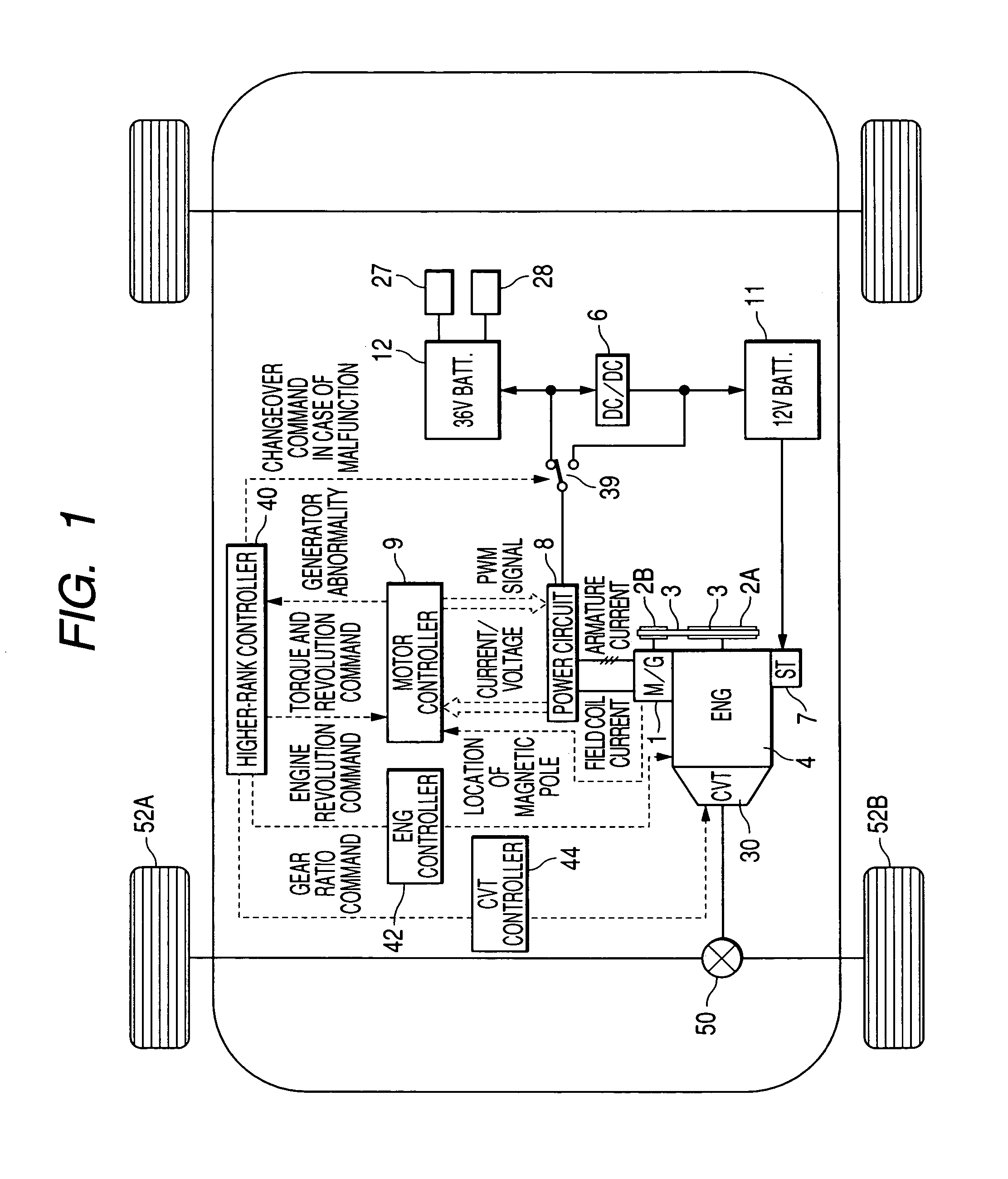
[0055]FIG. 1 is a block diagram that shows configuration of a vehicle which incorporates a power supply system for vehicle according to a first embodiment of the present invention.

[0056]Rotation speed of an engine 4 is changed by a CVT 30 and transmitted to wheels 52A and 52B via a differential gear 50, thereby running the vehicle. An engine controller 42 controls fuel injection and ignition timing for the engine 4 according to an engine revolution command issued by the higher-rank controller 40. The CVT 30 is controlled by a CVT controller 44 according to a transmission gear ratio command sent by the higher-rank controller 40.

[0057]Rotation of the engine 4 is transmitted to a motor g...

second embodiment

[0090]Next, with reference to FIGS. 8 through 10, configuration of a power supply system for vehicle which uses a vehicle generator according to the present invention will be explained.

[0091]First, by using FIG. 8, configuration of the major part of the vehicle that incorporates a power supply system for vehicle according to this embodiment will be explained.

[0092]FIG. 8 is a block diagram that shows configuration of the major part of the vehicle that incorporates a power supply system for vehicle according to a second embodiment of the present invention. The same numbers and symbols shown in FIG. 1 indicate the same parts.

[0093]The configuration of the power supply circuit according to this embodiment is different from that of FIG. 4; it does not use a changeover switch. If an abnormality occurs causing field coil current to stop flowing, the higher-rank controller 40 detects the abnormality and issues a command to the continuous and variable transmission unit CVT controller 44 to ...

third embodiment

[0112]Next, with reference to FIG. 11, configuration of a power supply system for vehicle which uses a vehicle generator according to the present invention will be explained.

[0113]FIG. 11 is a block diagram that shows configuration of a power supply system for vehicle according to a third embodiment of the present invention. Items are identical to those in FIGS. 1 and 2 when the same alphanumeric characters are assigned.

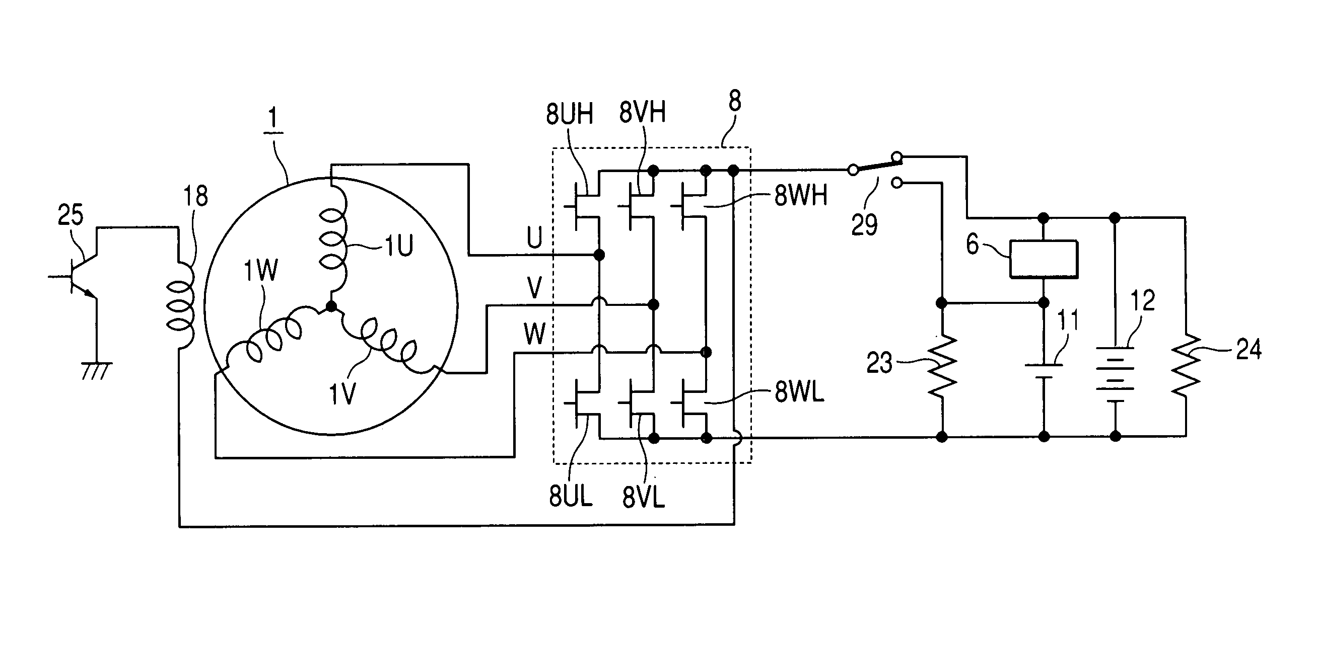
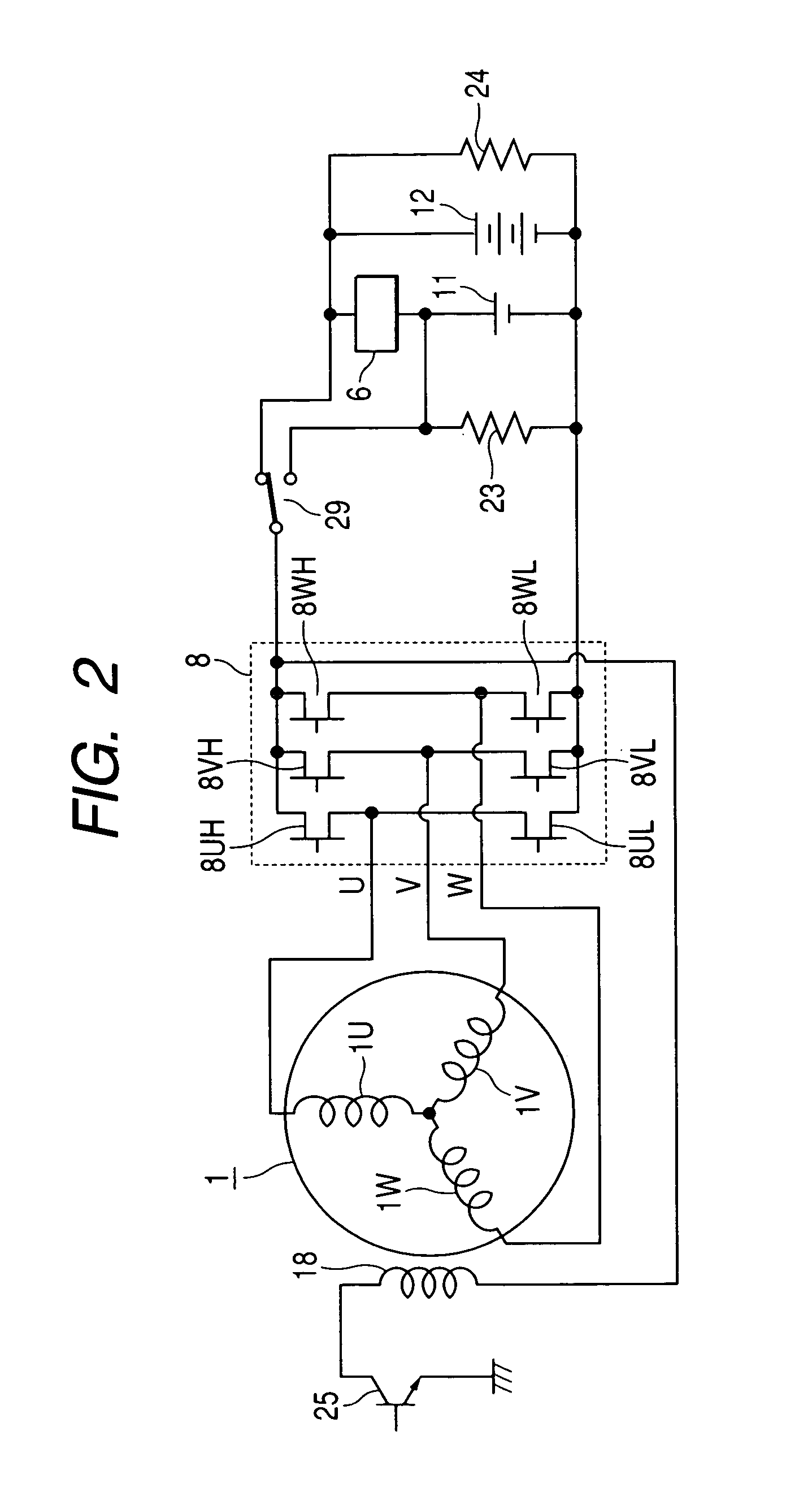
[0114]This embodiment is different from those shown in FIGS. 1 and 2 in that this embodiment uses a commutating circuit which comprises six diodes 31 instead of using a power circuit which comprises MOS-FETs shown in FIG. 2. In this embodiment, since the generator 1A is not used as a motor, it is a simple high-voltage generator. Two power supply systems, 36 V and 12 V, are provided, and the higher-rank controller 40 switches the switch 29 so that the generator 1 charges the high-voltage side 36-V battery 11 during normal operation. The generator 1A generates higher v...


PUM


Abstract

An A.C. generator has a rotor that is equipped with a permanent magnet and a field coil. The output of the A.C. generator charges the high-voltage battery. Voltage of the high-voltage battery is stepped-down by a DC / DC converter and supplied to the low-voltage battery. When the motor controller detects that the field coil has not been energized, the higher-rank controller switches so as to generate power by means of the permanent magnet of the A.C. generator and charge the low-voltage battery. This mechanism enables power to be generated when a circuit malfunctions.Thereby, a power supply system for vehicle can generate power when a circuit malfunctions so that the driver on the vehicle can drive the vehicle to a repair shop.

Description

CLAIM OF PRIORITY[0001]The present application claims priority from Japanese application serial no. 2004-240347, filed on Aug. 20, 2004, the content of which is hereby incorporated by reference into this application.FIELD OF THE INVENTION[0002]The present invention relates to a power supply system for vehicle, specifically relates to a power supply system that can operate when a generator for automobile is abnormally functioning.BACKGROUND OF THE INVENTION[0003]Recently, as the electrical components for an automobile increases, electric power generated only by a conventional 12-V low-voltage battery is not sufficient as the power supply on the automobile. Accordingly, a power supply system for vehicle has been proposed that is equipped with two battery systems: a 12-V low-voltage battery and a 36-V high-voltage battery. For example, as disclosed in Japanese Patent Laid-open No. 2001-28832, in a well-known power supply system for vehicle, a low-voltage battery and a high-voltage batt...

Claims


Application Information

Patent Timeline
Patent Type & Authority Patents(United States)
IPC IPC(8): F02D29/06
CPCB60R16/03H02J1/08H02J2001/008H02J2310/46H02J1/082
Inventor HINO, NORIAKIFUJINO, SHINICHIKANAZAWA, HIROSHIINNAMI, TOSHIYUKIKOBAYASHI, TAKASHI
Owner HITACHI LTD
Why Eureka
Try Eureka