Non-contact linear absolute position sensor

a position sensor and non-contact technology, applied in the field of position sensors, can solve the problems of affecting an otherwise accurate measurement, difficult to achieve good temperature compensation using hall effect sensors alone, and relative high degree of tolerability of parts, so as to achieve less predictable change in dimension, accurate output, and robustness.

Inactive Publication Date: 2007-05-08
DELPHI TECH INC
View PDF15 Cites 36 Cited by
  • Summary
  • Abstract
  • Description
  • Claims
  • Application Information

AI Technical Summary

Benefits of technology

[0011]In one embodiment, the first and second sensing units each include a pair of Hall Effect sensors. In each of the sensing units, one of the pair is oriented a pole's distance ahead of the other one of the pair so that each sensing unit produces dual signals 90° apart. This arrangement allows for temperature and target distance variation compensation, among other things. Accordingly, the inventive sensor system will be more robust to (i) variation of a material's magnetic properties, for example, between different lots of magnets, and variation with temperature; (ii) unpredictable target distance change due to temperature; and (iii) unpredictable target distance change due to application specific conditions (wear, pressure, etc.). For example, embodiments according to the invention may be made from plastic, which is characterized by a much less predictable change in dimension due to variation in temperature. The present invention can readily accommodate these uncertainties to provide an accurate output.

Problems solved by technology

Optical-based sensors are generally very accurate but require a relatively high degree of tolerancing on the parts, and are subject to strict sealing requirements in order to prevent or minimize dust from entering into the assembly, which can adversely influence an otherwise accurate measurement.
It is also very hard to achieve good temperature compensation using Hall Effect sensors alone.
This problem is increased when you have to compensate for a component's position variation due to temperature.

Method used


Image

  • Non-contact linear absolute position sensor
  • Non-contact linear absolute position sensor
  • Non-contact linear absolute position sensor

Examples


Embodiment Construction

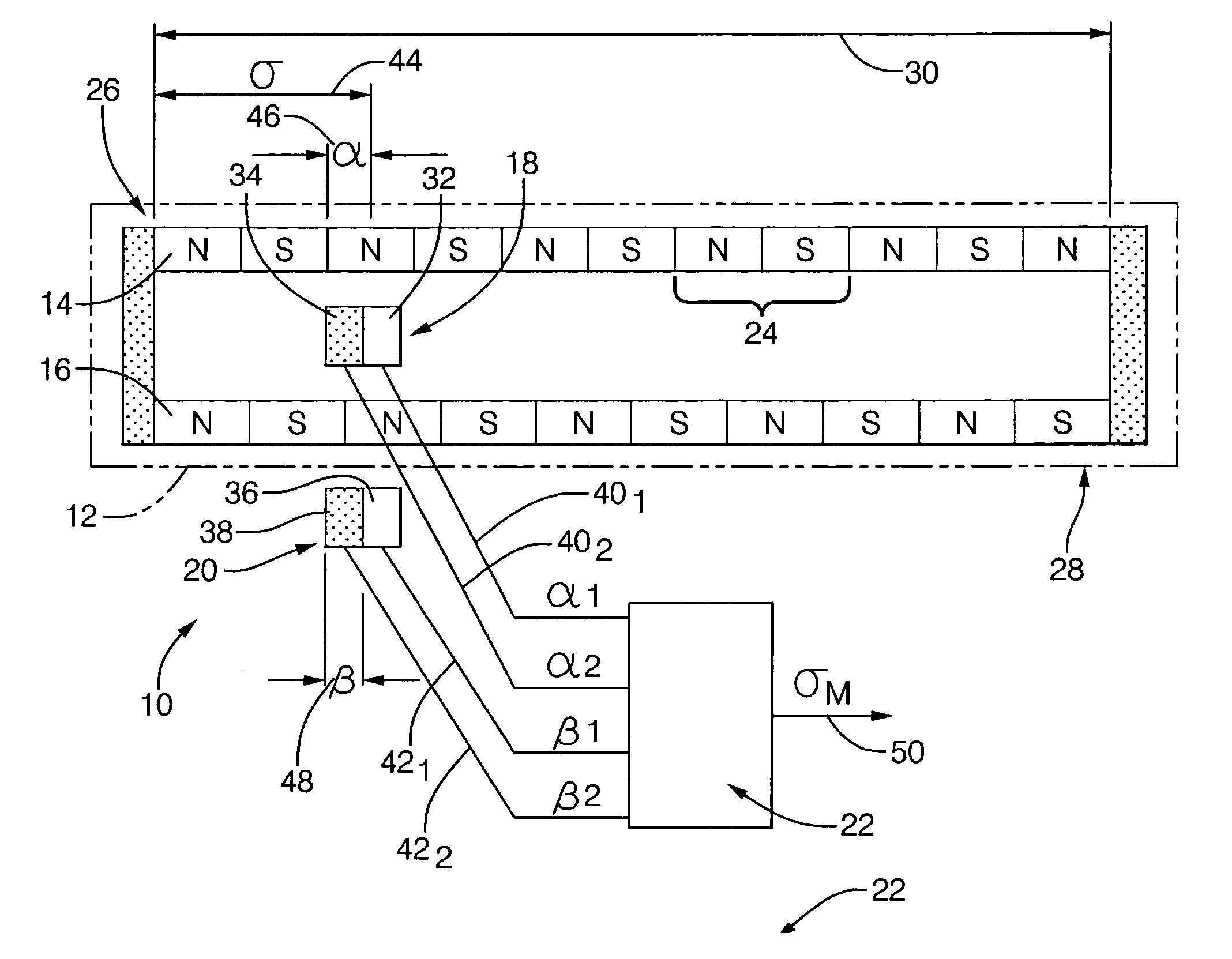
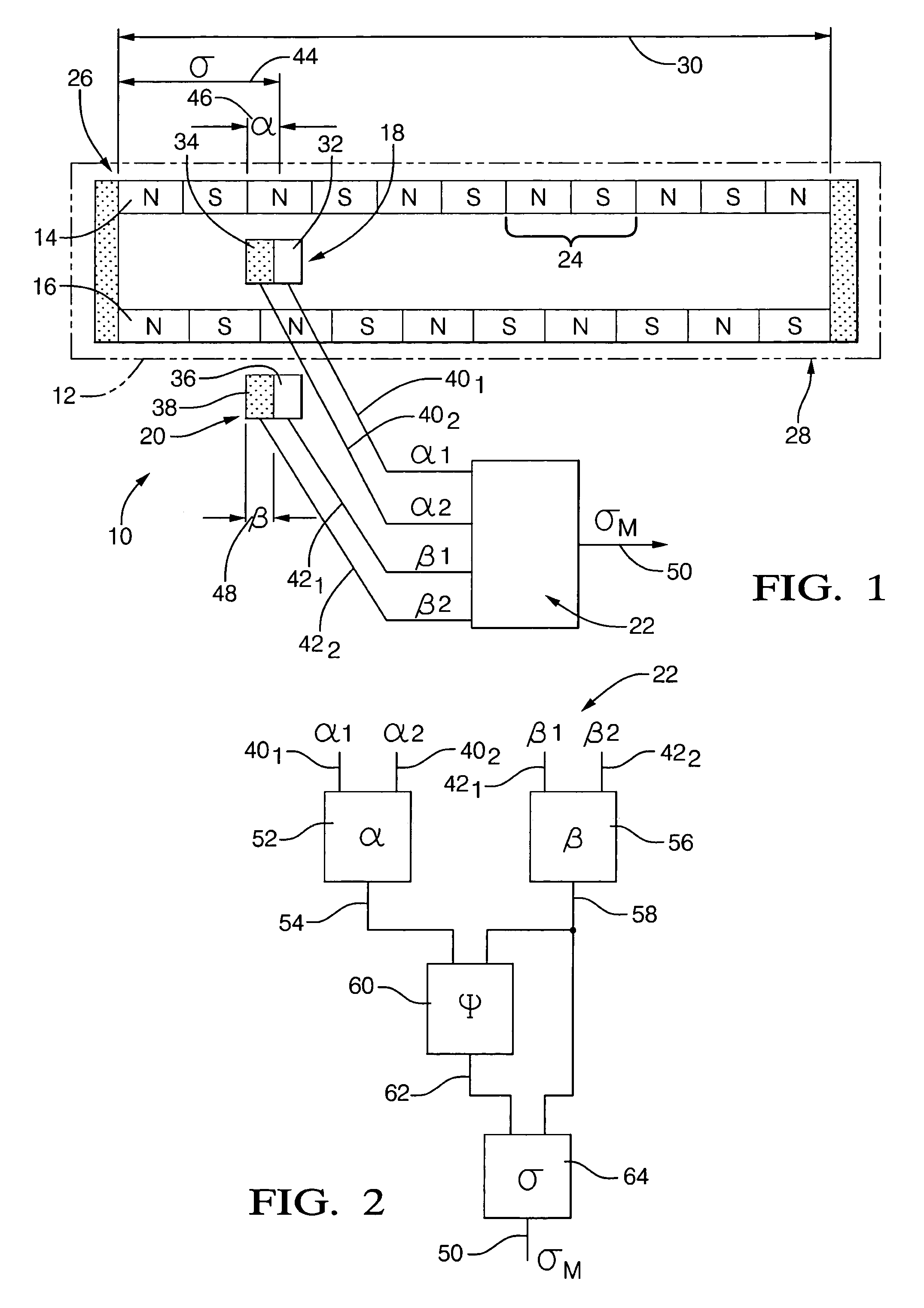
[0019]Referring now to the figures wherein like reference numerals are used to identify identical components in the various views, FIG. 1 is a schematic and block diagram view of a sensor system 10 in accordance with the present invention. Sensor system 10 is configured to provide an output signal indicative of an absolute linear position of a traveling body, for example, traveling body 12 (shown in phantom line) in FIG. 1.

[0020]The present invention provides for a non-contact sensor system, which avoids wear and tear, providing like-new performance even after long use. As will be described in greater detail below, a sensor system according to the invention also provides for accurate absolute linear position measurements even over temperature variations.

[0021]As described in the Background, there are many uses for a sensor system according to the invention. Examples include, but are not limited to, those mentioned in the Background, namely measuring long linear travel parts such as ...


PUM


Abstract

A non-contact linear absolute position sensor includes a first magnetic encoder having n+1 pole pairs, a second magnetic encoder having n pole pairs and located and aligned with the first magnetic encoder so as to cover a linear distance. The magnetic encoders are affixed to a traveling body. Two pairs of Hall Effect sensors are located near each of the first and second magnetic encoders and are configured to generate linear position signals. A processor is provided to process the linear position signals to generate an output signal indicative of a linear absolute position of the traveling body.

Description

BACKGROUND OF THE INVENTION[0001]1. Technical Field[0002]The present invention relates generally to position sensors, and, more particularly, to a non-contact linear absolute position sensor.[0003]2. Description of the Related Art[0004]Angular and linear position sensors are widely used in automatic control systems as feedback-sensing devices in one or more control loops of the system. In the automotive industry, such position information may be used in substitution of more traditional, conventional control feedback provided by mechanical linkages, such as cables, rods, and the like.[0005]For example, in the automotive field, it may be desirable to know the linear absolute position of a long travel mechanism, such as a rack and pinion mechanism (i.e., that moves when a driver of an automotive vehicle turns the steering wheel), or the position of a sliding door on a minivan. In the first example, a linear absolute position sensor can provide information as to the absolute linear posi...

Claims


Application Information

Patent Timeline
Patent Type & Authority Patents(United States)
IPC IPC(8): G01B7/14G01B7/30
CPCG01D5/145G01D5/2452
Inventor RECIO, MARIO A.GODOY, ARQUIMEDESMARTINEZ, DANIEL A.
Owner DELPHI TECH INC
Why Eureka
Try Eureka