Per-flow dynamic buffer management

a buffer management and per-flow technology, applied in the field of internetworking systems, can solve the problems of inefficient other flows, inability to handle well, drawbacks in cost, capacity and efficiency, and inefficiency when the number of flows increases

Inactive Publication Date: 2007-05-08
CISCO TECH INC
View PDF16 Cites 70 Cited by
  • Summary
  • Abstract
  • Description
  • Claims
  • Application Information

AI Technical Summary

Benefits of technology

[0020]The scheme operates independently of packet data rate and flow behavior, providing packet-specific means for rapidly discriminating well-behaved flows from aggressive, non-adapting (badly behaved) flows in order to manage buffer allocation accordingly. Additionally, the present invention adapts to changing flow requirements by fairly sharing buffer resources. The present invention handles robust, well-behaved flows that adapt to congestion situations signaled by packet drop, fairly sharing bandwidth among these flows. The present invention also ensures good service for fragile flows (those sending few packets and those of a time critical nature) such as Voice-over-Internet Protocol (VoIP), thereby protecting them from non-adapting aggressive flows (NAFs).

Problems solved by technology

A particular problem in internetworking traffic regulation arises from the variety of traffic sources or flows presented to the router / switching device.
Other flows, however, are not well-behaved.
This may be because the NAFs do not recognize the congestion, sometimes due to protocol incompatibilities, or (more likely) because they actually are trying to capture more router bandwidth.
The latter situation arises particularly in flows sent by sources that consider themselves higher priority than all others (hence the term “aggressive”); such priority assumptions by one flow are often in error in the modem, highly heterogeneous networks seen today.
As will be seen, however, all of these schemes have drawbacks in cost, capacity, and efficiency that suggest a better scheme is needed.
While FQ and its variants operate well when the number and variety of input flows is small and well-behaved, they becomes inefficient when the number of flows grows.
Clearly, a high number of flows requires a large number of queues, consuming a proportionally larger amount of resources, both in hardware and in operational complexity.
In the context of the modem, high volume networks seen today, this extra cost and complexity is undesirably inefficient.
This assumption has proven to be erroneous in the modern heterogeneous network.
Certain NAFs do not reduce flow rate and thus continue to take an unfair amount of router bandwidth simply because they counter packet drops with retransmissions.
As a further drawback, the random packet drops sometimes hit a fragile flow.
Fragile flows have the lowest tolerance for drops and delay, so a random packet drop management scheme can have a highly detrimental effect on them.
However, this scheme has the obvious drawback of high overhead associated with setting up a gating mechanism for each flow and administrative oversight.
Additionally, it lacks long-term flexibility to adapt to the wide variety and constantly changing mix of flow types seen in modem internetworking.
Typical prior art systems implement static buffer limitation schemes in software with limited hardware support.
All experience the same or similar drawbacks noted above due to overhead (set up and tear down, as well as processing time delay and hardware resource) costs.
Current schemes are unable to update their limit values fast enough to keep up with changing traffic conditions in the latest generation of ultra-fast (e.g., Gigabit speed) flows.
As an additional drawback, the use of TOS field 210 is not standardized among internetworking users.
Thus, neither TOS nor source address is a reliable means of identifying flow type at this time.

Method used


Image

  • Per-flow dynamic buffer management
  • Per-flow dynamic buffer management
  • Per-flow dynamic buffer management

Examples


embodiment

Hard and Soft Limiting Alternate Embodiment

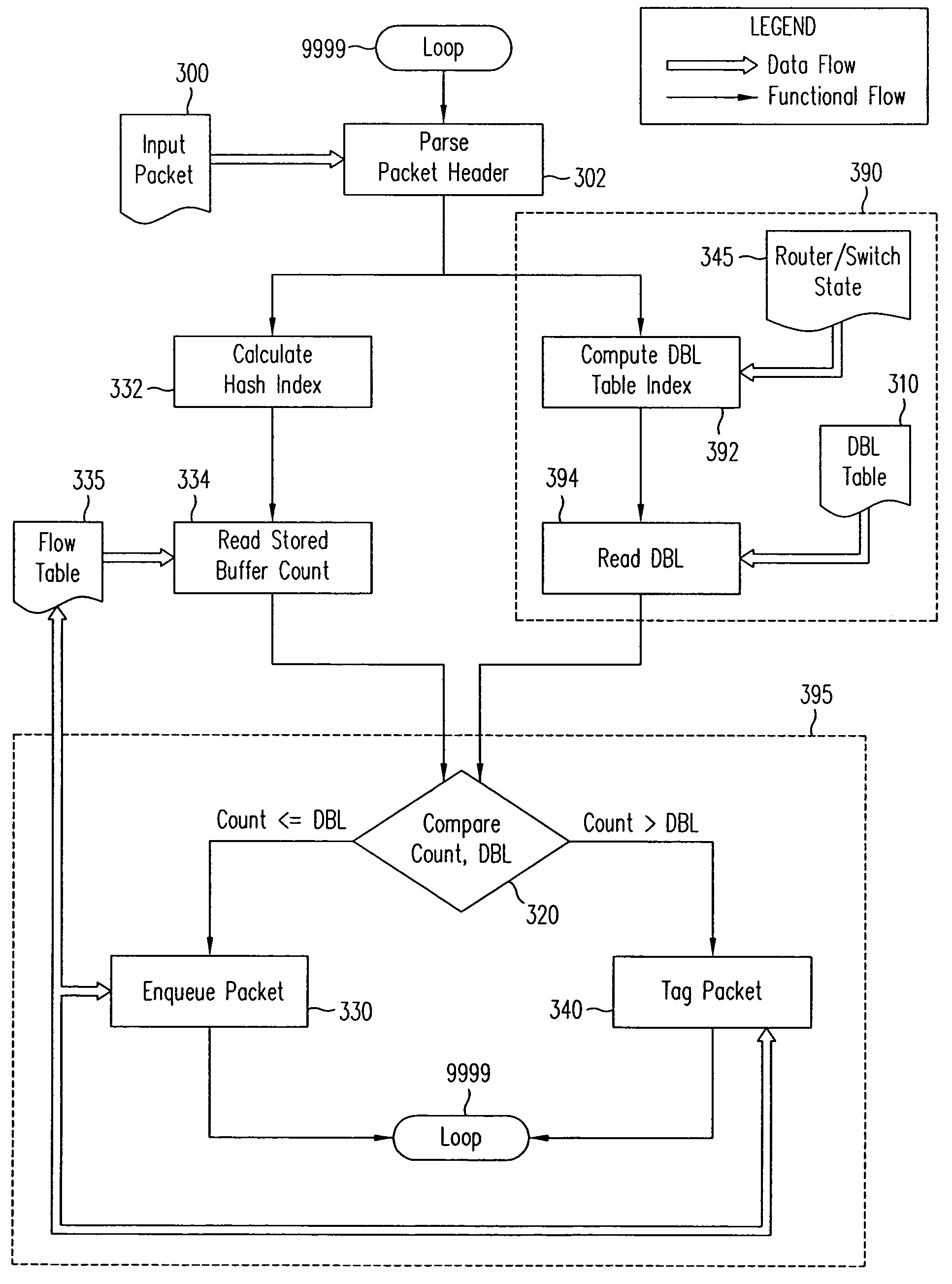
[0081]A further alternative embodiment implements soft and hard dynamic buffer limits, referring to FIG. 9. Comparison 905 determine the subsequent steps. If the stored buffer count in the flow table entry exceeds a soft limit value and is less than a hard limit (greater than dblMin but less than DBL) 920, the packet is tagged 340 as above. However, it is then dropped or marked based on random selection, i.e., qualification step 610, FIG. 6, is based on a random selection of mark or drop. Such probabilistic drop computations are known in the art and commonly employed in RED-type schemes. If the stored buffer count exceeds the hard limit (DBL) 930, the incoming packet is dropped 650 and the credit field for the flow in flow table 335 is decremented. For simplicity, the soft limit may be set to a fraction of the hard limit so that only the hard limit is non-trivially computed or looked up. Of course, if count is less than or equal to the soft...


PUM


Abstract

The present invention provides a per-flow dynamic buffer management scheme for a data communications device. With per-flow dynamic buffer limiting, the header information for each packet is mapped into an entry in a flow table, with a separate flow table provided for each output queue. Each flow table entry maintains a buffer count for the packets currently in the queue for each flow. On each packet enqueuing action, a dynamic buffer limit is computed for the flow and compared against the buffer count already used by the flow to make a mark, drop, or enqueue decision. A packet in a flow is dropped or marked if the buffer count is above the limit. Otherwise, the packet is enqueued and the buffer count incremented by the amount used by the newly-enqueued packet. The scheme operates independently of packet data rate and flow behavior, providing means for rapidly discriminating well-behaved flows from non-well-behaved flows in order to manage buffer allocation accordingly. Additionally, the present invention adapts to changing flow requirements by fairly sharing buffer resources among both well-behaved and non-well-behaved flows.

Description

[0001]This application is a continuation of U.S. patent application Ser. No. 10 / 307,805 (now U.S. Pat. No. 6,829,217), entitled “Per-Flow Dynamic Buffer Management,” filed Dec. 2, 2002 and naming Andreas V. Bechtolsheim and David R. Cheriton as inventors, which in turn is a continuation of U.S. patent application Ser. No. 09 / 238,552 (now U.S. Pat. No. 6,515,963), entitled “Per-Flow Dynamic Buffer Management,” filed Jan. 27, 1999, and naming Andreas V. Bechtolsheim and David R. Cheriton as inventors. The above-referenced applications are hereby incorporated by reference herein in their entirety.BACKGROUND OF THE INVENTION[0002]1. Field of the Invention[0003]The present invention relates to internetworking systems and in particular to methods and apparatus for managing traffic flow in routers and switches.[0004]2. Description of the Related Art[0005]Internetworking encompasses all facets of communications between and among computer networks. Such communications data flow streams may i...

Claims


Application Information

Patent Timeline
Patent Type & Authority Patents(United States)
IPC IPC(8): H04L12/56
CPCH04L47/2441H04L47/30H04L49/90H04L49/9005H04L47/31H04L47/32
Inventor BECHTOLSHEIM, ANDREAS V.CHERITON, DAVID R.
Owner CISCO TECH INC
Why Eureka
Try Eureka