Optical isolator utilizing a micro-resonator

a micro-resonator and optical isolator technology, applied in the field of optical isolators, can solve the problems of inability to reduce the thickness of the faraday rotator, the device is relatively large and expensive, and the inability to use in large-scale optical signal processing systems

Inactive Publication Date: 2007-05-08
AVAGO TECH WIRELESS IP SINGAPORE PTE
View PDF10 Cites 33 Cited by
  • Summary
  • Abstract
  • Description
  • Claims
  • Application Information

AI Technical Summary

Problems solved by technology

Such devices are relatively large and expensive, and hence, poorly suited for use in large-scale optical signal processing systems.
In particular, the thickness of the Faraday rotator cannot be reduced, since the amount of rotation per unit length of material in the rotator depends on the physical properties of the materials used.
In addition, integration of these optical isolators with waveguides and other processing optical elements that are formed on a common substrate is difficult with these designs.

Method used


Image

  • Optical isolator utilizing a micro-resonator
  • Optical isolator utilizing a micro-resonator
  • Optical isolator utilizing a micro-resonator

Examples


Embodiment Construction

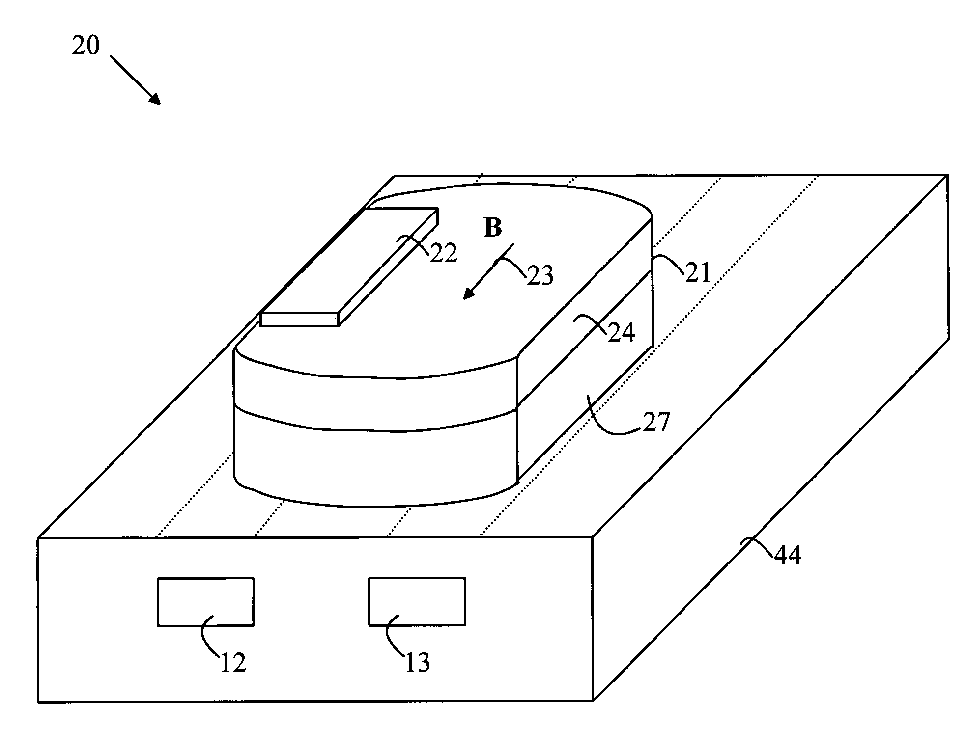
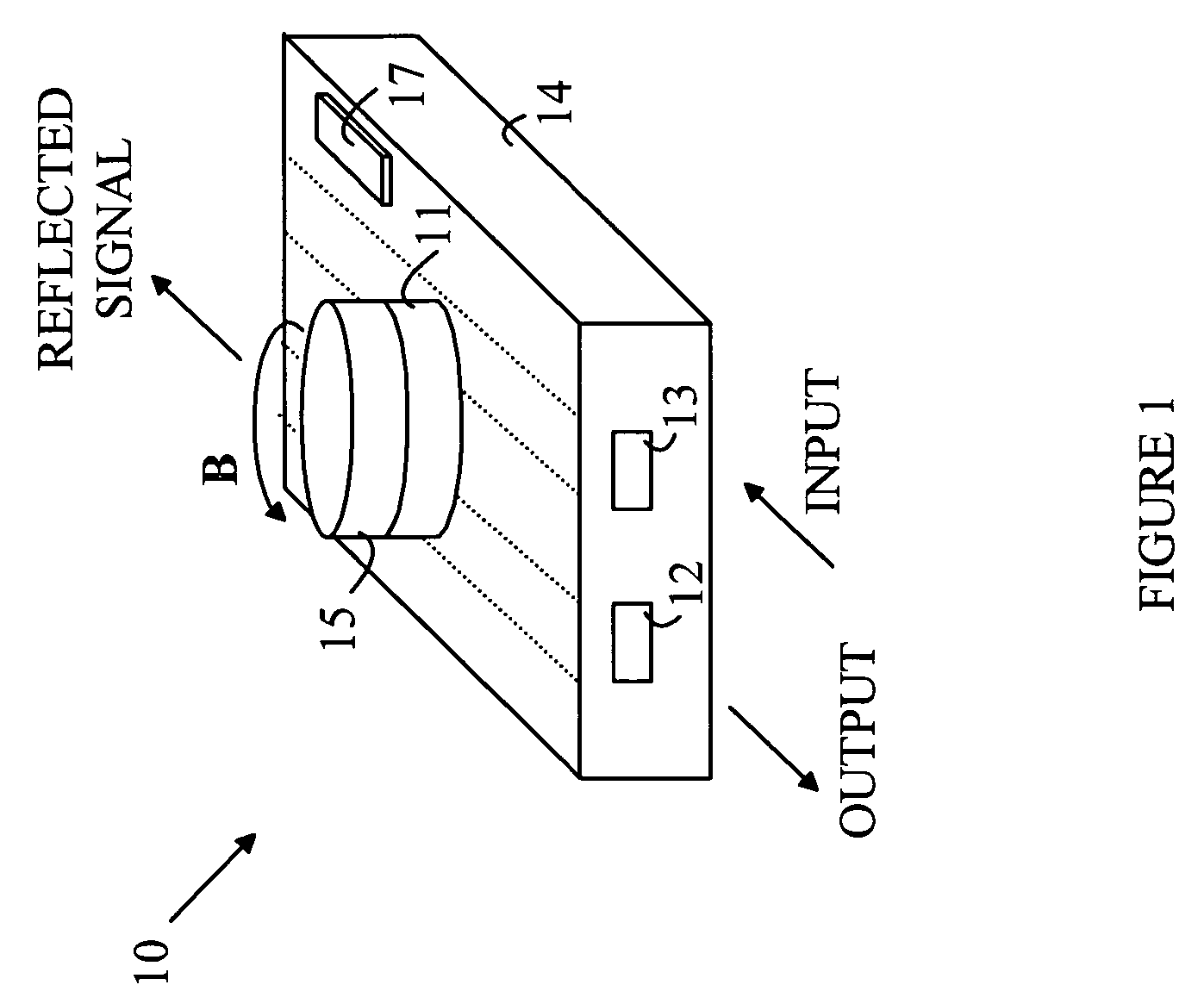
[0016]The manner in which the present invention provides its advantages can be more easily understood with reference to FIG. 1, which is a perspective view of an optical isolator according to one embodiment of the present invention. Optical isolator 10 is based on a microdisk resonator and operates in a manner similar to a wavelength routing switch. Optical isolator 10 includes first and second waveguides constructed in a substrate 14 and a microdisk resonator optimally coupled to the waveguides. The waveguides are shown at 12 and 13, and the resonator is shown at 11.

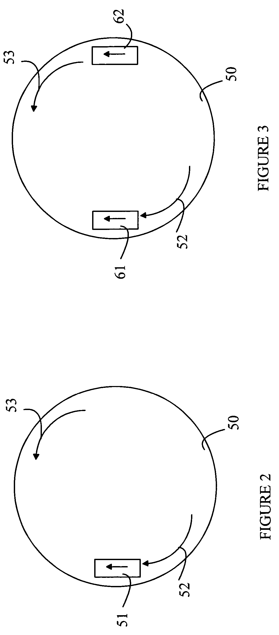
[0017]Microdisk resonator 11 will couple energy from waveguide 13 to waveguide 12 only if the wavelength of the optical signal propagating in the input waveguide matches one of the resonant wavelengths of the traveling wave mode in microdisk resonator 11. At resonance, complete energy transfer occurs between the input and output waveguides. The passband bandwidth of the isolator is determined by the coupling coefficient...


PUM

PropertyMeasurementUnit
thickaaaaaaaaaa
diametersaaaaaaaaaa
widthaaaaaaaaaa

Abstract

An optical isolator for coupling light from a first waveguide to a second waveguide is disclosed. The optical isolator utilizes a resonator coupled to the first and second optical waveguides. The resonator has a resonance at λ for light traveling from the first optical waveguide to the second optical waveguide; however, the resonator does not have a resonance at λ for light traveling from the second waveguide to the first waveguide. The resonator can use a layer of ferromagnetic material in an applied magnetic field. The magnetic field within the ferromagnetic material varies in strength and / or direction over the layer of ferromagnetic material. The magnetic field can be generated by an external magnetic field that varies over the layer of ferromagnetic material. Alternatively, the resonator can include a layer of ferromagnetic metal that overlies a portion of the layer of ferromagnetic material and a constant external magnetic field.

Description

FIELD OF THE INVENTION [0001]The present invention relates to integrated optical components, and more particularly, to optical isolators.BACKGROUND OF THE INVENTION [0002]The ever-increasing demand for broadband communication systems has led to optical transmission systems based on optical waveguides such as fiber optics and optical processing elements for use in these systems. To decrease the cost of such systems, large-scale integration of the optical devices is needed. Large-scale integration also provides decreased size and increased reliability.[0003]One optical device that is used in such systems is an optical isolator. In optical communication systems, optical signals pass through interfaces that generate reflected signals that propagate back to the signal source. Optical isolators are used to block these reflected signals from reaching the source. Ideally, optical isolators transmit the optical signal in the forward direction and block the reflected light signal that is trav...

Claims


Application Information

Patent Timeline
Patent Type & Authority Patents(United States)
IPC IPC(8): G02B6/26G02B6/34G02F1/09G02B27/28G02F1/095H04B10/00
CPCG02B6/12007G02B6/2746G02B6/29335G02F1/0955G02B2006/12097G02B2006/12104G02F2203/15
Inventor TAN, MICHAEL R. T.TRUTNA, WILLIAMBOUR, DAVID P.LEARY, MICHAEL H.
Owner AVAGO TECH WIRELESS IP SINGAPORE PTE
Why Eureka
Try Eureka