Rolling bearing unit with sensor

a technology of rolling bearings and sensors, applied in the direction of instruments, force/torque/work measurement apparatuses, transportation and packaging, etc., can solve the problems of high cost and the inability to accurately calculate the ground contact load from the measurement of strain sensors, and achieve the effect of convenient assembly

Inactive Publication Date: 2007-05-15
JTEKT CORP
View PDF32 Cites 12 Cited by
  • Summary
  • Abstract
  • Description
  • Claims
  • Application Information

AI Technical Summary

Benefits of technology

[0007]An object of the present invention is to provide a sensor-equipped antifriction bearing unit which is adapted to detect the speed of rotation by a simple construction without necessitating the member to be detected which is conventionally needed.
[0008]Another object of the invention is to provide a sensor-equipped antifriction bearing unit which is adapted to accurately determine the load acting on the bearing by a simple construction and which is also adapted to detect the speed of rotation of the rotation-side raceway member of the bearing, so that when the bearing unit is used as a hub unit in motor vehicles, the ground contact load and the rotational speed of the wheel can be determined with high accuracy by the simple construction.DISCLOSURE OF THE INVENTION
[0016]With the sensor-equipped antifriction bearing unit of the present invention, gap variations produced, for example, by the eccentricity of the rotation-side raceway member are detected by the magnetostrictive sensor. This obviates the need for the member to be detected, such as a pulser ring or magnetized pulser, for detecting rotation, consequently decreasing the number of assembling steps and the number of components to result in a cost reduction.
[0019]With the sensor-equipped antifriction bearing unit having the processing means which comprises a unit for averaging the output values of the magnetostrictive sensor, and a load calculating unit for determining the load from the averaged output, the gap between the rotation-side raceway member and the fixed-side raceway member is detected by the magnetostrictive sensor, and the output of the sensor, i.e., voltage values output therefrom, are averaged. This ensures proportional relationship between the voltage average and the load acting on the bearing, with the result that the load on the bearing can be determined from the output of the magnetostrictive sensor with high accuracy.
[0020]Accordingly, when the sensor-equipped antifriction bearing unit is used for the hub unit of motor vehicles, the force exerted by the ground on the rotation-side raceway member, i.e., ground contact load, can be detected with high accuracy from the gap between the rotation-side raceway member and the fixed-side raceway member. The ground contact load on the tire thus obtained is used as data substituting for the slip ratio in ABS control and is useful also for drive force control and braking force control, contributing to the improvement of accuracy of vehicle control. Because the bearing unit has the rotation detecting unit for determining the speed of rotation of the rotation-side raceway member from the number of repetitions of the variation in the output of the magnetostrictive sensor, the number of revolutions of the wheel or the rotational speed thereof can be detected from the number of repetitions of the variation in the gap, in addition to the ground contact load on the tire. Thus, two kinds of important vehicle control data can be obtained by using one sensor.
[0022]When the bearing unit is to be used as the sensor-equipped hub unit, the magnetostrictive sensor may be so provided as to be opposed to an outer periphery of a crimp portion for preventing the inner ring from slipping off, or as to be opposed to an outer periphery of the inner shaft. When the sensor is fixed to the end portion of the fixed-side raceway member so as to be opposed to the outer periphery of the inner ring, a signal line from the sensor can be let out from the end portion of the fixed-side raceway member. This renders the bearing unit easy to assemble. The magnetostrictive sensor can be attached to the fixed-side raceway member easily for example, by embedding the sensor in a resin and joining the resin to the fixed-side raceway member or to a cover or the like fixed to this member.

Problems solved by technology

The units therefore have the problem of necessitating an increased number of assembling steps and a larger number of components to result in a higher cost.
However, the sensor-equipped hub unit disclosed in the third-mentioned publication has the problem that since the strain of the annular support member is measured, a great error is involved in determining the ground contact load from the strain measured, consequently making it impossible to calculate the ground contact load accurately from the measurement of the strain sensor.

Method used


Image

  • Rolling bearing unit with sensor
  • Rolling bearing unit with sensor
  • Rolling bearing unit with sensor

Examples


Embodiment Construction

[0030]Embodiments of the invention will be described below with reference to the drawings.

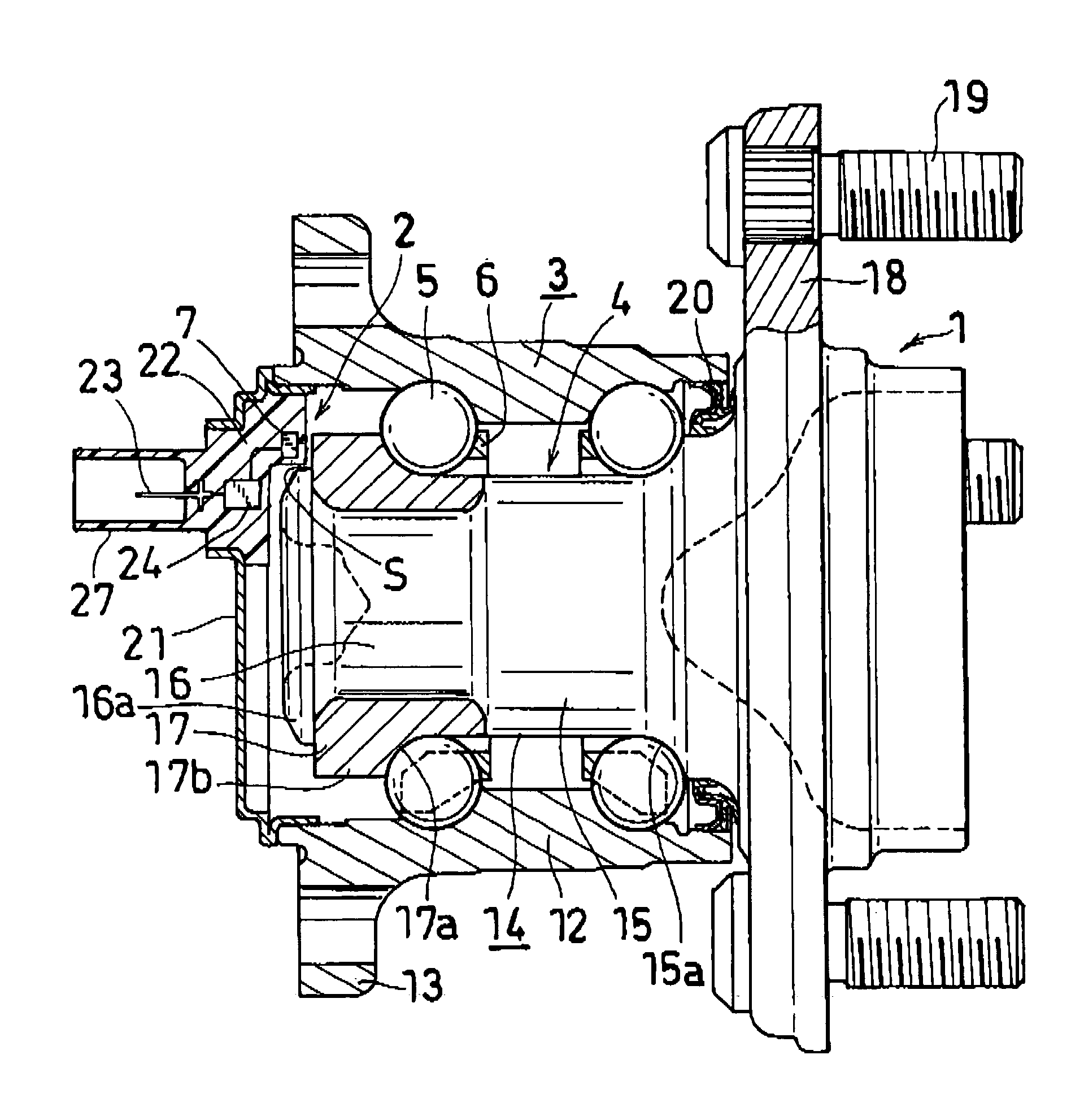
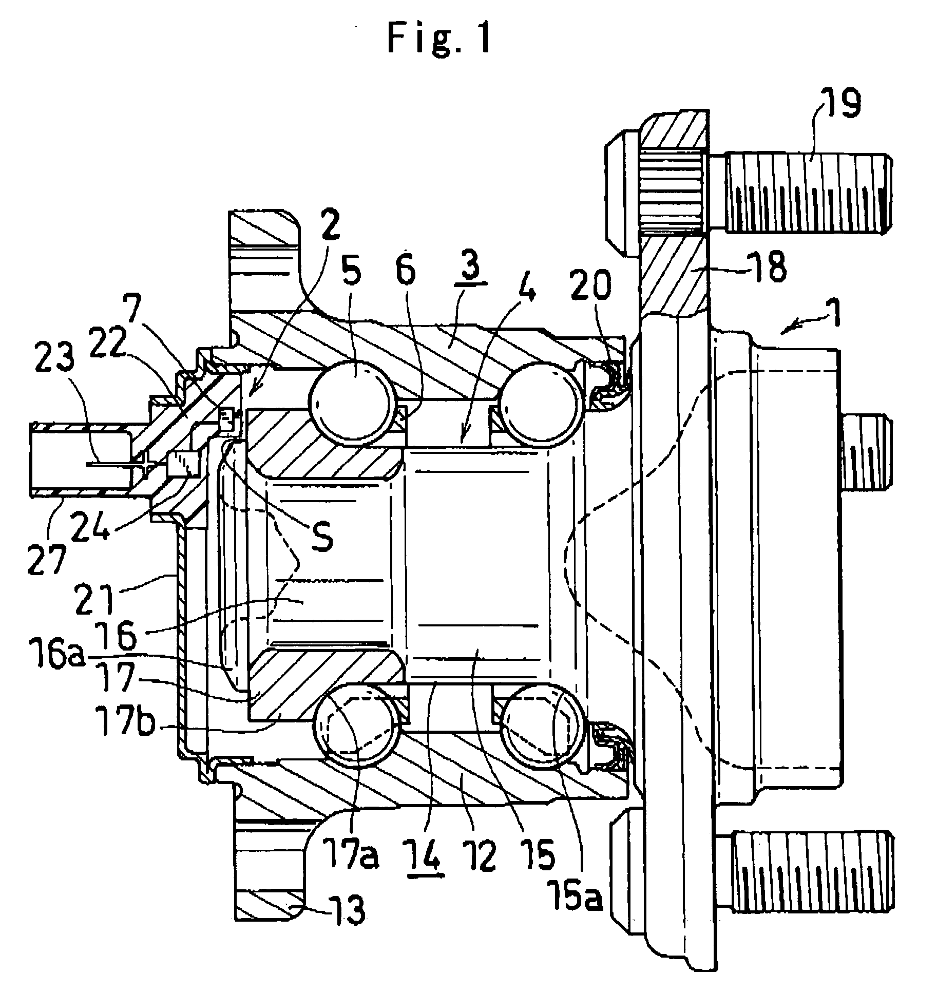
[0031]FIG. 1 shows a first embodiment of sensor-equipped antifriction bearing unit of the invention. In the following description, the terms “left,”“right,”“upper” and “lower” refer respectively to the left- and right-hand sides and the upper and lower sides of FIGS. 1 to 3. Incidentally, the left-hand side of these drawings is the inside of the vehicle and the right-hand side thereof the outside of the vehicle.

[0032]As shown in FIG. 1, the sensor-equipped antifriction bearing unit comprises a hub unit 1 serving as an antifriction bearing, and a sensor device 2 for detecting the rotation thereof and ground contact loads.

[0033]The hub unit 1 comprises a fixed-side raceway member 3 fixed to a vehicle body, a rotation-side raceway member 4 for a wheel to be attached to, balls 5 serving as rolling bodies arranged in two rows between the two members 3, 4, and retainers 6 for holding the balls 5 in t...


PUM

PropertyMeasurementUnit
voltageaaaaaaaaaa
speedaaaaaaaaaa
magnetostrictiveaaaaaaaaaa

Abstract

A sensor device 2 has a magnetostrictive sensor 8 provided on a fixed-side raceway member 3 for detecting a gap between the sensor and a rotation-side raceway member 4, and means for processing the output of the magnetostrictive sensor 8. The processing means comprises a rotation detecting unit for determining the speed of rotation of the rotation-side raceway member 4 from the number of repetitions of a variation in the output of the magnetostrictive sensor 8, a unit for averaging output values of the magnetostrictive sensor 8 and a load calculating unit for determining the load acting on an antifriction bearing from the output averaged by the averaging unit.

Description

TECHNICAL FIELD[0001]The present invention relates to sensor-equipped antifriction bearing units comprising an antifriction bearing and a sensor device attached to the bearing for detecting various items of data as to the bearing.BACKGROUND ART[0002]Antifriction bearing units are already known which comprise an antifriction bearing, and a sensor device and a member to be detected, the sensor device and the member to be detected being mounted on the bearing. Such units are used in railroad cars and motor vehicles for supporting an axle or a rotating shaft for transmitting rotation to the axle and for detecting the rotation, i.e., the speed of rotation of the axle or shaft or the angle of rotation thereof.[0003]The publication of JP-U No. 6-47867 discloses such a sensor-equipped antifriction bearing unit comprising a sensor device which is a rotational speed sensor of the electromagnetic induction type and a member to be detected which is in the form of an annular member (pulser ring)...

Claims


Application Information

Patent Timeline
Patent Type & Authority Patents(United States)
IPC IPC(8): G01L3/14F16C19/18F16C19/52F16C33/58F16C33/72G01L5/00G01P3/44G01P3/487G01P3/488
CPCF16C19/186F16C33/723F16C41/007G01L5/0023G01P3/44F16C41/008G01P3/446G01P3/487G01P3/488G01P3/443F16C2326/02F16C19/52F16C33/58G01L5/00
Inventor KOYAGI, KATSURAINOUE, MASAHIRO
Owner JTEKT CORP
Why Eureka
Try Eureka