
Candle wick snuffer

Inactive Publication Date: 2007-05-15
BAIRD IAN F
View PDF28 Cites 2 Cited by
  • Summary
  • Abstract
  • Description
  • Claims
  • Application Information

AI Technical Summary

Benefits of technology

[0007]It is a purpose and advantage of the present invention to provide an improved candle wick snuffer which is incorporated into the base of the candle and which snuffs the flame and the wick when the candle fuel gets low.
[0008]It is another purpose and advantage of this invention to provide a candle wick snuffer which can be incorporated into the candle structure so that, when the candle fuel gets low, the candle wick snuffer is released to snuff the flame in the candle wick.
[0009]It is a further purpose and advantage of this invention to provide a candle wick snuffer which can be economically employed to increase the safety of candles.
[0010]It is a further purpose and advantage of this invention to provide a candle wick snuffer which is mounted on a baseplate, which also holds the bottom of the wick. The baseplate carries a stressed spring which is retained by temperature-sensitive adhesive so that, when the candle burns down, rising temperature releases the spring-loaded snuffer to extinguish the flame in the candle wick.
[0011]Other purposes and advantages of this invention will become apparent from a study of the following portion of the specification, the claims and the attached drawings.

Problems solved by technology

Popularity has increased usage and, according to the National Fire Protection Association (NFPA), candles contribute to a high incidence of fires, causing injuries and loss of life as well as property damage in the millions of dollars.
Typically, as a candle flame burns downward to the bottom of the candle, the fuel is depleted and the wick burns out.
In a freestanding candle, where the structure itself is also its fuel, a problem arises when the remaining fuel bottom loses its structure and evolves into a hot molten pool.
If not adequately placed on a non-combustible surface, the molten fuel can saturate and ignite the supporting structure, producing a fire.
A candle in a container has a different problem due to the fact the fuel's heat is intensified.
Excessive heat alone can scorch the paint or labels off of metal containers and crack or break glass containers, spilling forth the remaining contents, presenting a fire hazard.
Migration to an outer wall causes burning through and spilling molten fuel and the lit wick, setting the stage for a fire.
If the burning wick is adjacent to an outer wall, it becomes a fire hazard.
The candle bottom which once had structure is reduced to a molten state, now presenting a potential for fire.

Method used


Image

  • Candle wick snuffer
  • Candle wick snuffer
  • Candle wick snuffer

Examples


Embodiment Construction

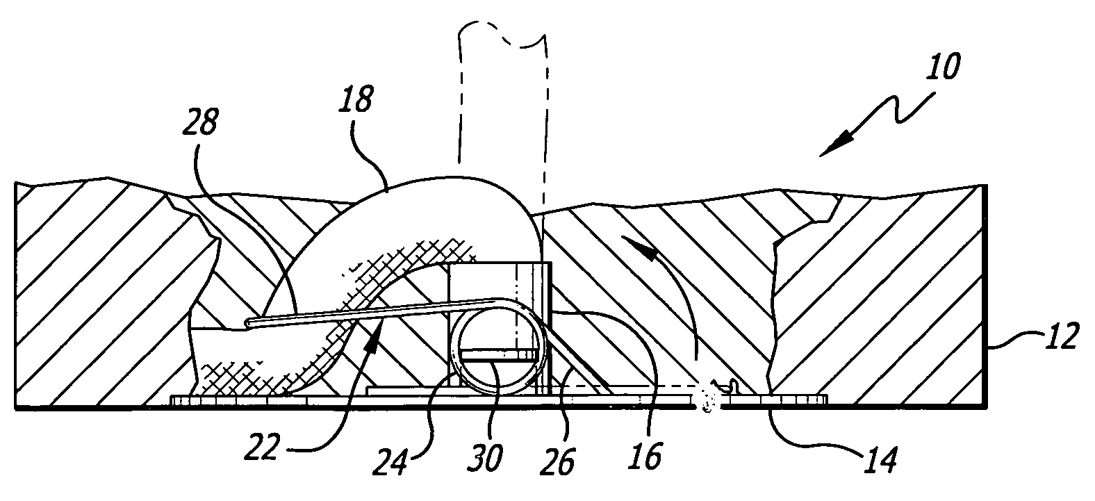
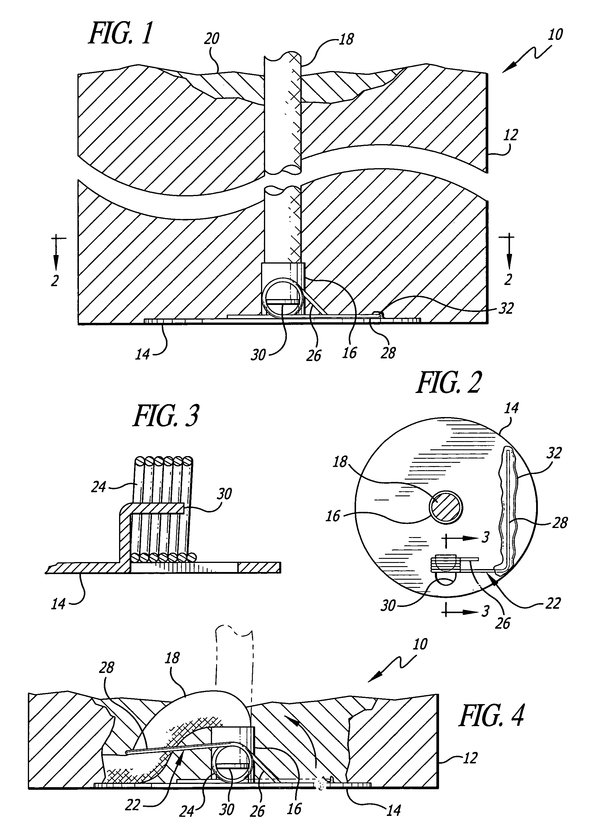
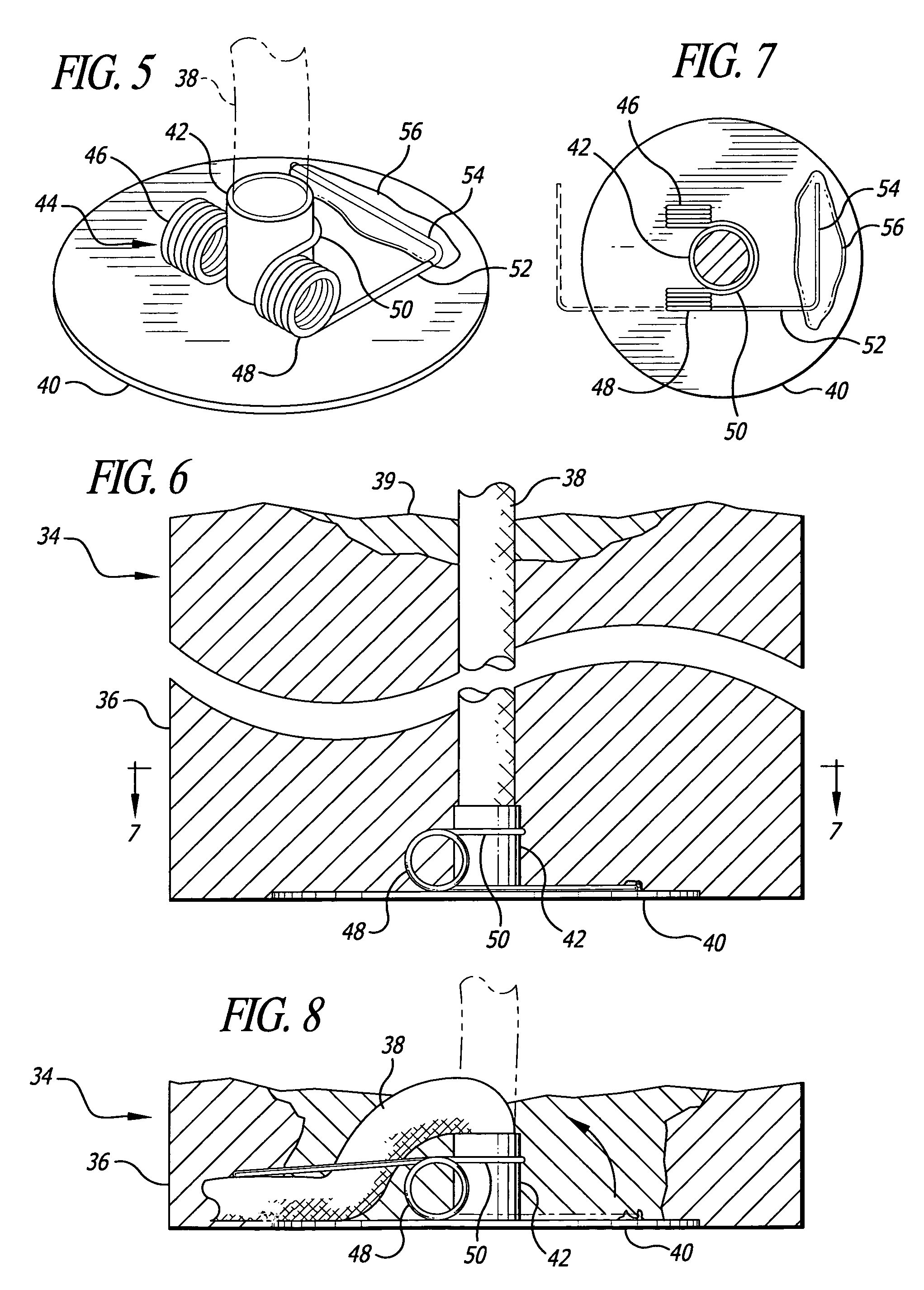
[0024]Candle 10, shown in FIGS. 1 and 4, is formed of a body of solid fuel 12. At the bottom of the candle 12 is a baseplate 14, which is seen in FIGS. 1, 2, 3 and 4. The baseplate has a nose or collar 16 formed thereon, usually by punching up from the bottom. The collar can be of different heights, depending on the method of formation. Furthermore, it may not even be in the form of a collar, but a punchout in the baseplate to which a wick can be attached. The purpose of the collar is to hold the bottom end of wick 18 onto the baseplate, which secures the wick in place. The structure is known in the trade as a “wick sustainer.” The wick may be positioned within the body of the candle by any conventional means, including forming the body around the wick or forming the fuel body, making a hole therethrough and placing the wick in the hole. When the wick is lit, the heat from the flame forms the liquid fuel pool 20. The liquid fuel moves up the wick by means of capillary action. The li...


PUM


Abstract

The candle wick snuffer is mounted on a baseplate which is at the bottom of the candle. The baseplate carries a swing arm which is released when the temperature rises to critical point in the bottom of the candle. The baseplate may also carry a wick retainer to maintain the correct relative position between the swing arm of the candle wick snuffer and the wick. When the swing arm is released, it pulls the remaining wick down to snuff the candle flame.

Description

CROSS REFERENCE[0001]This application relies on prior Provisional Application Ser. No. 60 / 559,852, filed Apr. 5, 2004, for priority.BACKGROUND OF THE INVENTION[0002]Candles have been around for thousands of years. First used fuels were animal fat or tallow and later bees wax, then came the paraffin and vegetable based wax, and now an even newer synthetic polymer type of fuel. For candle fuels to burn, capillary action is employed. A fibrous material or cotton wick draws the liquid fuel up to the flame. Candles have evolved over time, and many additions have been added, such as color, fragrance, oil and novelty objects. The reasons to burn candles other than just for providing light are vast in number. Popularity has increased usage and, according to the National Fire Protection Association (NFPA), candles contribute to a high incidence of fires, causing injuries and loss of life as well as property damage in the millions of dollars.[0003]The Fire Analysis and Research Division of NF...

Claims


Application Information

Patent Timeline
IPC IPC(8): F21V35/00
CPCF21V35/00
Inventor BAIRD, IAN F.
Owner BAIRD IAN F
Learn More