Method of manufacturing a soft hearing aid

a manufacturing method and hearing aid technology, applied in the field of hearing aids, can solve the problems of not fully achieving the expectations of the market, not fully fostering the overall market growth, and the intermodulation of the frequency response cannot be completely resolved, and achieve the effect of a wide range of gain

Inactive Publication Date: 2007-05-15
SOFTEAR TECH L L C
View PDF44 Cites 34 Cited by
  • Summary
  • Abstract
  • Description
  • Claims
  • Application Information

AI Technical Summary

Benefits of technology

[0032]The hearing aid of the present invention provides a greater range of gain before feedback occurs.

Problems solved by technology

Those expectations have not been fully realized.
While these developments have solved many of the problems associated with traditional electronic design and steadily gained market share, they have not fostered overall market growth.
The issues of early acoustic feedback, less than optimum fidelity and intermodulation of the frequency response cannot be completely resolved by electronic manipulation of the signal by either analog or digital means.
Historically, custom-molded ear worn hearing instruments have been limited to an “acrylic pour” process as the means of the construction.
However, it is still often necessary to return the device for shell modifications.
In direct contrast to electronic advances within the industry, little or no advancement has been realized in custom prosthetic design.
In addition, the pivot action causes displacement of the device resulting in unwanted acoustic feedback.
This problem has necessitated countless shell modifications, thereby compromising the precision approach of the original dental technology.
Canal motion makes it very difficult to achieve a comfortable, true acoustic seal with hard acrylic material.
These cavities are transient because they change with jaw motion as a function of time, resulting in impedance changes in the ear canal.
These transients compromise the electroacoustic performance.
The properties of hard acrylic have limitations that require modification to the hard shell exterior to accommodate anatomical variants and the dynamic nature of the ear canal.
The peripheral acoustic leakage caused by these modifications results in acoustic feedback before sufficient amplification can be attained.
The resulting feedback requires electronic modifications to “tweak” the product to a compromised performance or a “pseudo-perfection”.
As a result, the industry still falls well short of an audiological optimum.
Unfortunately, soft vinyl materials shrink, discolor, and harden after a relatively short period of wear.
Polyurethane has proven to provide a better acoustic seal than polyvinyl, but has an even shorter wear life (approximately three months).
Silicones have a long wear life but are difficult to bond with plastics such as acrylic, a necessary process for the construction of custom hearing instruments.
The fact remains, however, that the entire ear is a dynamic acoustic environment and is ill-served by a rigid material such as acrylic.

Method used


Image

  • Method of manufacturing a soft hearing aid
  • Method of manufacturing a soft hearing aid
  • Method of manufacturing a soft hearing aid

Examples


Embodiment Construction

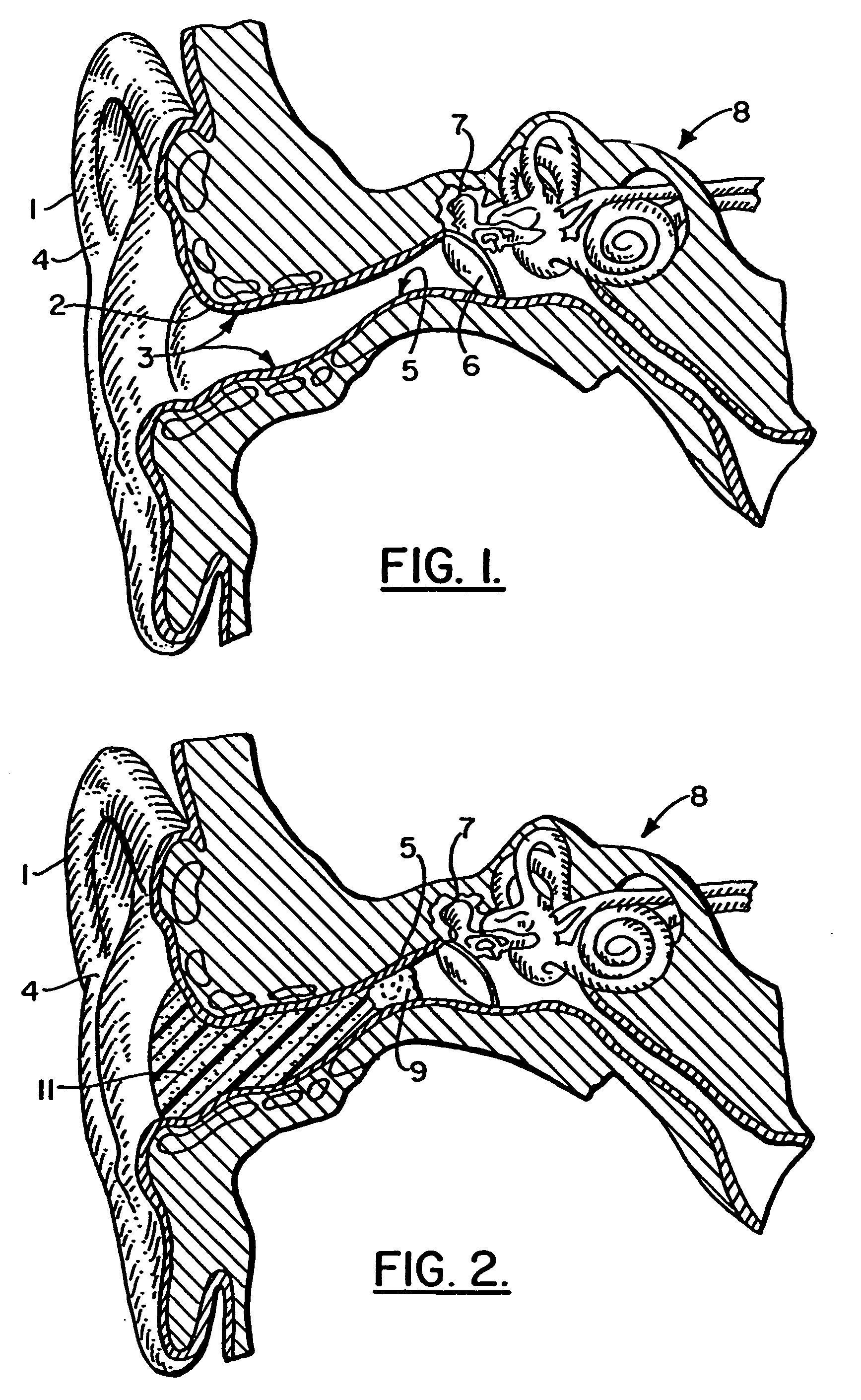
[0069]FIGS. 1 and 2 show a user's ear 1 and anatomical parts of the ear. In FIG. 1 there can be seen the external auditory canal 2, ear canal wall 3, auricle 4, isthmus 5, tympanic membrane 6, middle ear 7 and inner ear 8. In FIG. 2 a dam 9 such as a cotton dam or otoblock dam is positioned at the isthmus 5. The dam 9 is used as a first step of an embodiment of the method of the present invention wherein a form portion 11 or impression material is formed of silicone, methylmethacrylate or alginate. The form 11 is formed in between dam 9 and auricle 4 as shown in FIG. 2.

[0070]During the method step of making form 11, the form 11 conforms to all of the curvatures of the ear canal 3 so that an accurate form 11 is provided for making a female mold.

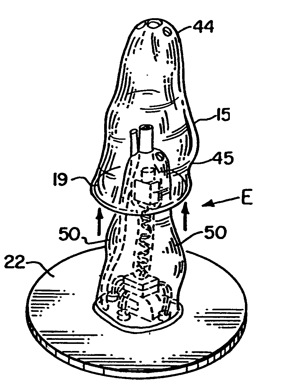
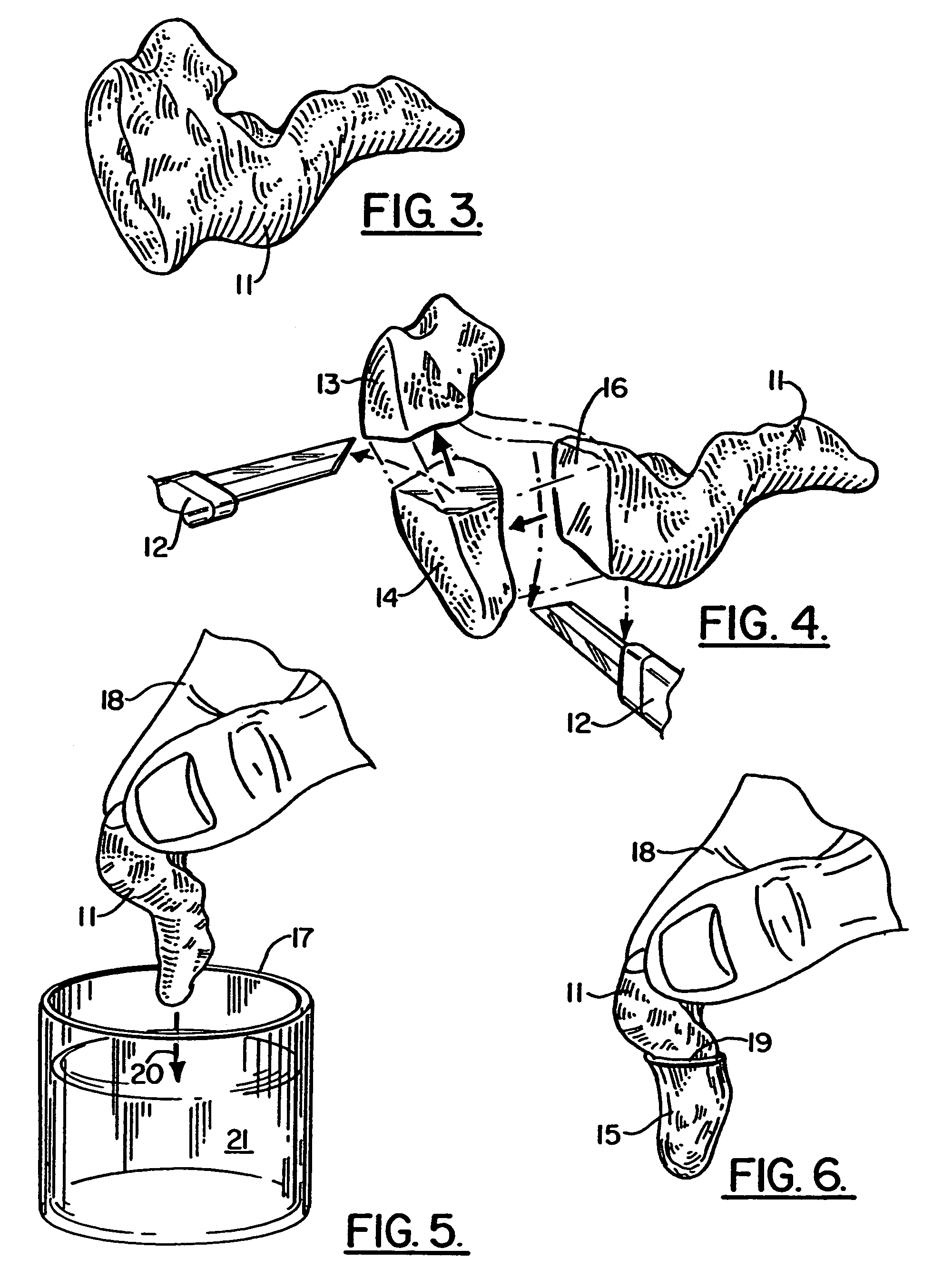
[0071]The female mold 15 is shown in FIGS. 6 and 9–12. In FIGS. 3 and 4, the form 11 is shown after being removed from the ear 1 (FIG. 3) and during a cutting of the form 11 using knives 12 to cut excess material that is designated as 13, 14 i...


PUM

PropertyMeasurementUnit
thicknessaaaaaaaaaa
thicknessaaaaaaaaaa
thicknessaaaaaaaaaa

Abstract

A method of manufacturing a hearing aid preferably includes the steps of: placing a moldable material in the ear canal of a patient to cast a form; using the form to form a hollow shell with an outer surface that approximates the shape of the patient's ear canal, the shell being of a soft polymeric material providing a mounting member; mounting electronic hearing aid components to the mounting member; joining the mounting member to the hollow shell to define a mold cavity; and filling the shell with a soft polymeric material that substantially encapsulates at least one of the electronic components and bonds to the mounting member, wherein the combination of shell, electronic components and soft polymeric material define a soft structure that is compliant to ear canal movement during use.

Description

CROSS-REFERENCE TO RELATED APPLICATIONS[0001]This application is a continuation-in-part of U.S. patent application Ser. No. 09 / 855,095, filed 14 May 2001 (now U.S. Pat. No. 6,695,943), which is a continuation-in-part of U.S. patent application Ser. No. 09 / 311,156, filed 13 May 1999 (now U.S. Pat. No. 6,354,990), which is a continuation-in-part of U.S. patent application Ser. No. 09 / 181,539 now U.S. Pat. No. 6,728,383, Ser. No. 09 / 181,540 (now U.S. Pat. No. 6,432,247), Ser. No. 09 / 181,541 (now U.S. Pat. No. 6,438,244), Ser. No. 09 / 181,842 (now U.S. Pat. No. 6,254,526), Ser. No. 09 / 181,843 (now U.S. Pat. No. 6,434,248), Ser. No. 09 / 181,844 (now U.S. Pat. No. 6,228,020) and Ser. No. 09 / 181,845 (now U.S. Pat. No. 6,473,512), all filed 28 Oct. 1998, which are continuations-in-part of U.S. patent application Ser. No. 09 / 084,864, filed 26 May 1998 (now U.S. Pat. No. 6,022,311). Each of these patent applications and patents are incorporated herein by reference. Priority of each of these pat...

Claims


Application Information

Patent Timeline
Patent Type & Authority Patents(United States)
IPC IPC(8): B29C33/40B29C33/42C07D493/10C07H15/26C07H19/16H04R25/00
CPCC07D493/10C07H15/26C07H19/16H04R25/456H04R25/658H04R25/652H04R25/60H04R25/65Y10T156/1994H04R2225/023H04R2225/025H04R2460/11Y10T156/11H04R25/603H04R25/609H04R2225/57
Inventor JUNEAU, ROGER P.CREEL, LYNN P.DESPORTE, EDWARD J.MAJOR, MICHAELSIEGLE, GREGORY R.KINLER, KELLY M.
Owner SOFTEAR TECH L L C
Why Eureka
Try Eureka