
Adjustable data loading circuit with dynamic test mode switching for testing programmable integrated circuits

a technology of programmable integrated circuits and loading circuits, applied in the field of circuit testing, can solve the problems of large number of free input pins and large delay in speed testing arrangements, and achieve the effects of increasing bandwidth, low bandwidth, and high loading bandwidth

Inactive Publication Date: 2007-05-15
ALTERA CORP
View PDF7 Cites 11 Cited by
  • Summary
  • Abstract
  • Description
  • Claims
  • Application Information

AI Technical Summary

Benefits of technology

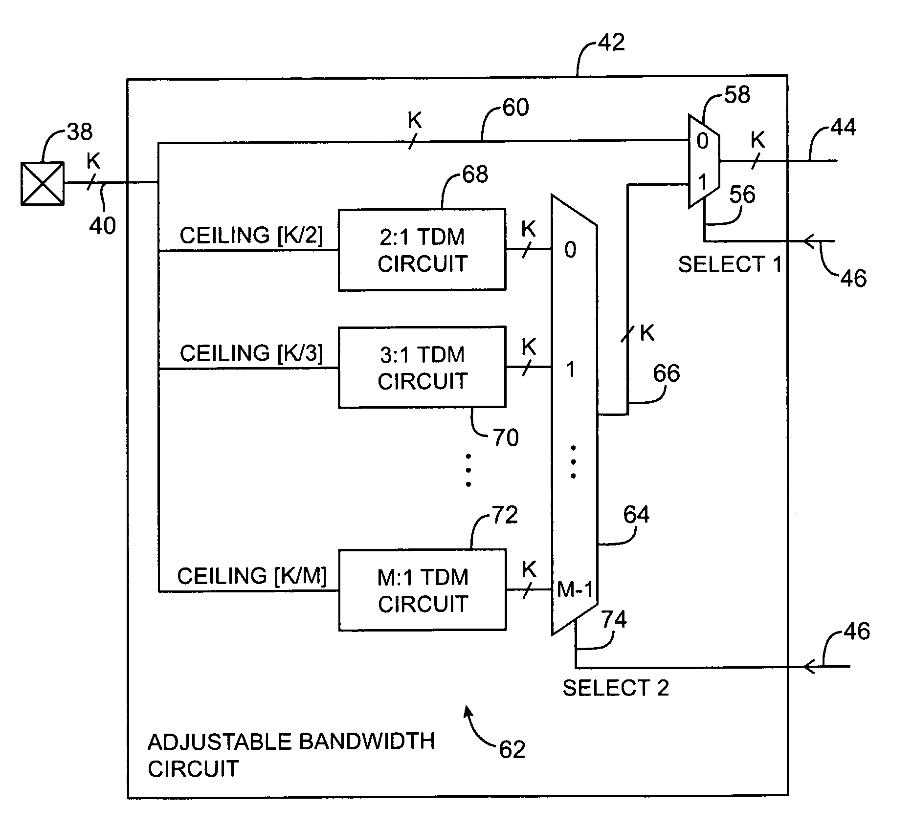
[0009]When it is desired to load test configuration data into the programmable elements using relatively few input pins, the test configuration data loading circuit is configured so that the test data from relatively few input pins is routed to all of the parallel test configuration data loading lines. In this configuration, the test configuration data loading circuit has a relatively low bandwidth. When it is desired to load test configuration data into the programmable elements at high speed, a relatively larger number of input pins may be used to increase bandwidth. In this situation, the test configuration data loading circuit is configured so that it supplies a higher loading bandwidth in which the test data from the larger number of input pins is routed to the test configuration data lines. Loading speed is maximized at the expense of using a larger test data input bus width.

Problems solved by technology

In a production environment, this is a considerable delay.
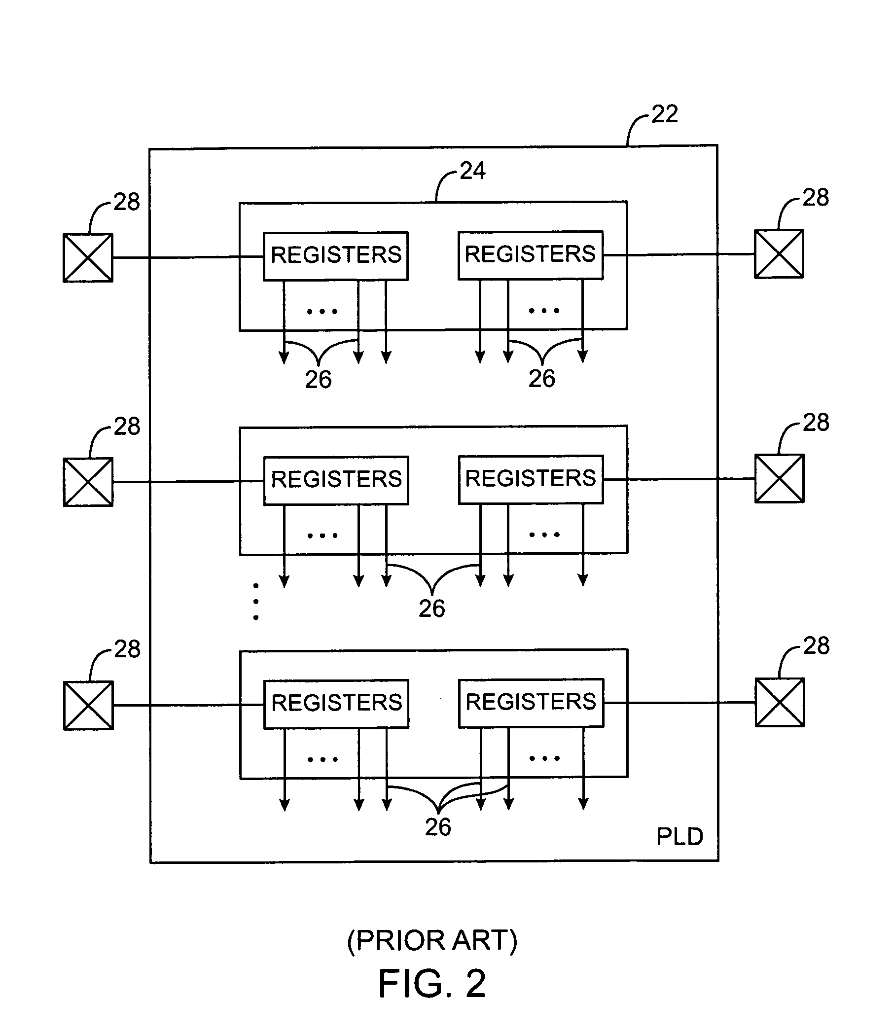
However, such high-speed testing arrangements require large numbers of free input pins, which are not always available, particularly with smaller packages.

Method used


Image

  • Adjustable data loading circuit with dynamic test mode switching for testing programmable integrated circuits
  • Adjustable data loading circuit with dynamic test mode switching for testing programmable integrated circuits
  • Adjustable data loading circuit with dynamic test mode switching for testing programmable integrated circuits

Examples


Embodiment Construction

[0030]The present invention relates to testing integrated circuits. In particular, the invention relates to circuitry that is incorporated into integrated circuits to facilitate testing and to systems and methods for performing testing operations.

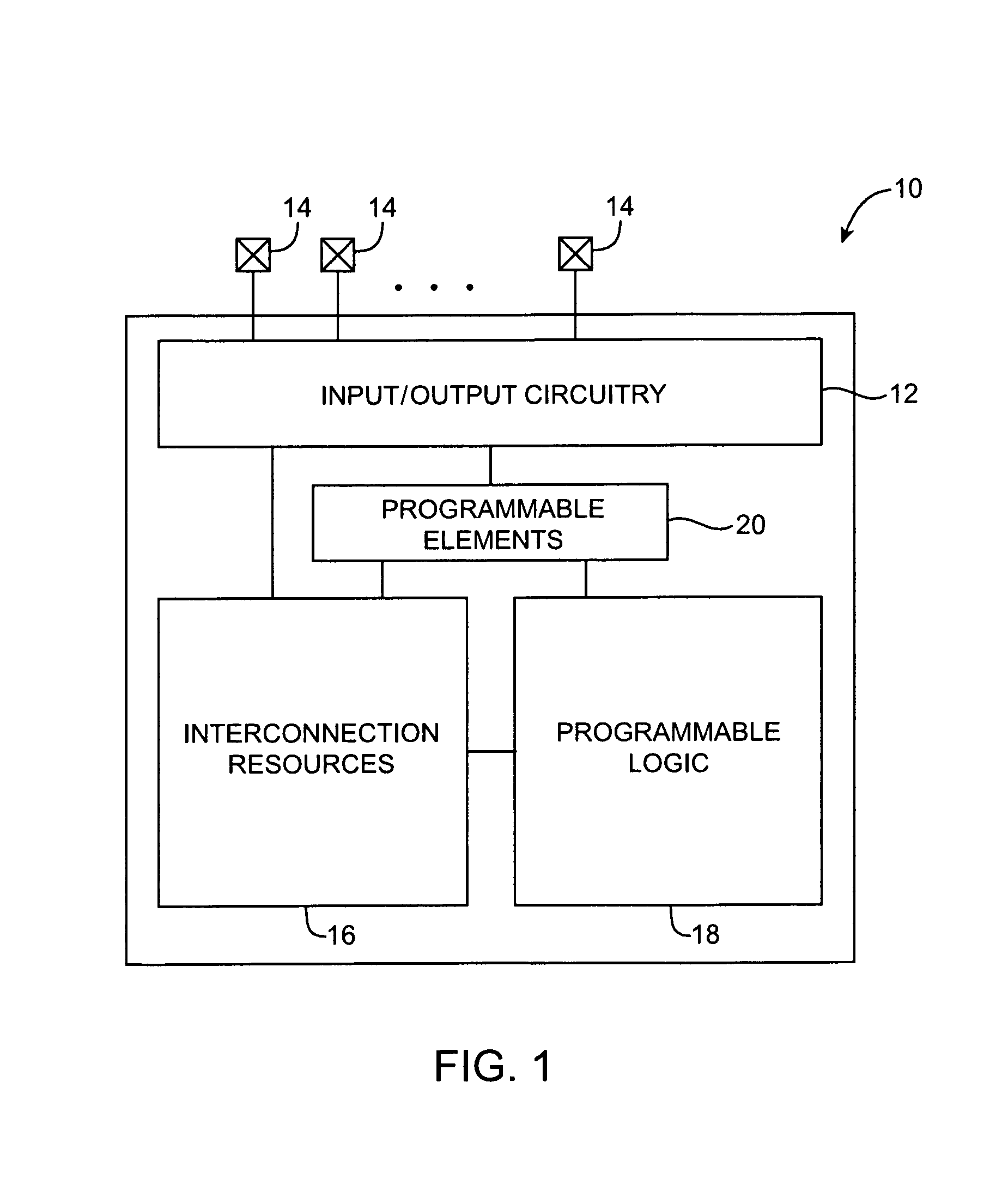
[0031]The integrated circuits being tested in accordance with the invention may be, for example, programmable logic devices. The invention also applies to the testing of integrated circuits with programmable capabilities that are not typically referred to as “programmable logic devices.” Such programmable integrated circuits may include, for example, application specific integrated circuits with regions of programmable logic, digital signal processors containing programmable logic, microprocessors or microcontrollers with programmable logic regions, etc. Aspects of the invention may also apply to integrated circuits that do not contain significant amounts of programmable logic. For clarity, however, the present invention will be described i...


PUM


Abstract

Methods and apparatus for testing programmable integrated circuits are provided. Programmable integrated circuits include programmable elements that are loaded with configuration data to program programmable logic to perform a custom logic function. The programmable integrated circuits receive test configuration data from a tester to program the programmable logic into a test configuration. After the programmable integrated circuit has been placed into the test configuration by loading the test configuration data, test vectors are applied to the programmable integrated circuit to evaluate its performance. Test configuration data loading circuits are used in the programmable integrated circuits to control how the test configuration data is loaded into the programmable elements. When the adjustable circuits are placed in a low bandwidth configuration, relatively few input lines are used to load the test configuration data. When the adjustable circuits are placed in a high bandwidth configuration, test data can be loaded quickly.

Description

BACKGROUND OF THE INVENTION[0001]This invention relates to circuit testing, and more particularly, to circuits with dynamic test mode switching capabilities for use when testing programmable integrated circuits such as programmable logic device integrated circuits.[0002]Programmable logic devices are a type of integrated circuit that can be customized by a user to implement a desired logic design. In a typical scenario, a logic designer uses a logic design system to design a logic circuit. The logic design system uses information on the hardware capabilities of a given programmable logic device to help the designer implement the logic circuit using the resources available on that given programmable logic device. The logic design system creates configuration data. When the configuration data is loaded into the programmable logic device, it programs the logic of the programmable logic device so that the programmable logic device implements the designer's logic circuit.[0003]To test a ...

Claims


Application Information

Patent Timeline
IPC IPC(8): H03K19/00
CPCG01R31/31919
Inventor HO, ENG LING
Owner ALTERA CORP
Learn More