
Preceding vehicle recognition apparatus

a vehicle recognition and preceding vehicle technology, applied in the direction of distance measurement, pedestrian/occupant safety arrangement, instruments, etc., can solve the problems of difficult to keep track of the movement or the locus of the preceding vehicle with a high degree of reliability, and the conventional apparatus is no longer able to detect the position of the left and right edges, etc., to achieve the effect of increasing the width maintaining the resolution of the preceding vehicle, and high degree of precision

Active Publication Date: 2007-05-15
DENSO CORP
View PDF19 Cites 11 Cited by
  • Summary
  • Abstract
  • Description
  • Claims
  • Application Information

AI Technical Summary

Benefits of technology

The present invention provides a preceding vehicle recognition apparatus that can continuously recognize a preceding vehicle even when reflected signals cannot be obtained from its reflectors temporarily or continuously. The apparatus uses received signals reflected by the vehicle's reflectors to compute the positions of the reflectors and calculates the area of the vehicle's rear face by integrating a predetermined number of received signals. This allows for relatively high precision in calculating the area of the rear face of the preceding vehicle, even when only one reflector is detected. This enhances the recognition of the preceding vehicle and helps track its movement.

Problems solved by technology

However, when the reflectors are dirty or the preceding vehicle is traveling along a curved road, for example, it is difficult to detect the reflectors in some cases.
In such cases, the conventional apparatus is no longer capable of detecting the positions of the left and right edges on sides of the rear face of the preceding vehicle.
It is therefore difficult to keep track of the movement or the locus of the preceding vehicle with a high degree of reliability.

Method used


Image

  • Preceding vehicle recognition apparatus
  • Preceding vehicle recognition apparatus
  • Preceding vehicle recognition apparatus

Examples


Embodiment Construction

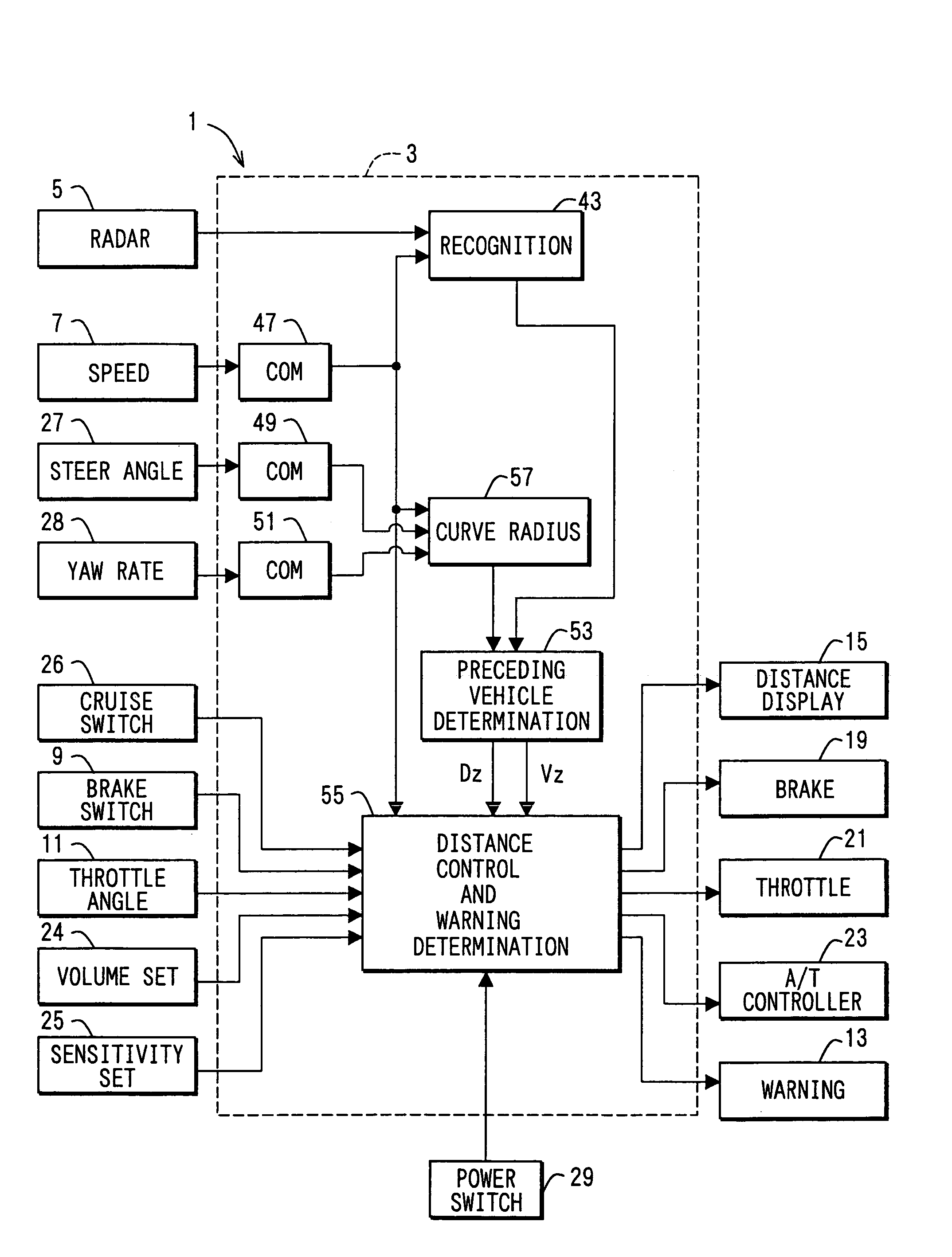
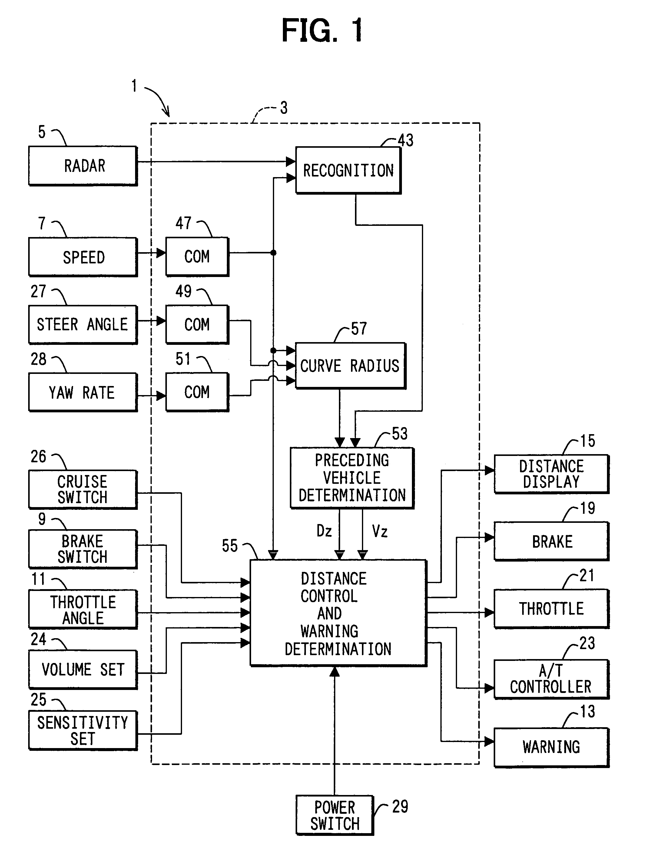
[0030]As shown in FIG. 1, a vehicle control apparatus 1 includes a recognition / inter-vehicle distance control ECU 3 as a core component. The control ECU 3 has a configuration mainly based on a microcomputer in addition to I / O (Input / Output) interfaces, a variety of driving circuits and a variety of detection circuits.

[0031]The control ECU 3 inputs a variety of detection signals from a laser radar sensor 5 serving as a vehicle radar apparatus, a vehicle speed sensor 7, a brake switch 9 and a throttle opening sensor 11. The control ECU 3 outputs a variety of driving signals to a warning-sound generator 13, a distance display unit 15, a brake driver 19, a throttle driver 21 and an automatic transmission controller 23. In addition, the control ECU 3 is also connected to a warning sound volume setter 24 for setting a warning sound volume, a warning sensitivity setter 25 for setting a sensitivity in a warning determination process, a cruise control switch 26, a steering angle sensor 27 fo...


PUM


Abstract

A preceding vehicle recognition apparatus detects positions of two reflectors provided on a preceding vehicle from individual received signals each representing a signal reflected by the reflectors. The apparatus further detects position of an area of rear face of the preceding vehicle by integrating a plurality of received signals each representing a signal reflected by the body of the preceding vehicle. Thus, even when only one of the two reflectors is detected or both reflectors cannot be detected, the width of the preceding vehicle can be found. By using the width of the preceding vehicle, it is possible to keep track of the movement of the same preceding vehicle with a high degree of reliability.

Description

CROSS REFERENCE TO RELATED APPLICATION[0001]This application is based on and incorporates herein by reference Japanese Patent Application No. 2004-134421 filed on Apr. 28, 2004.FIELD OF THE INVENTION[0002]The present invention relates to a preceding vehicle recognition apparatus for continuously recognizing a preceding vehicle while identifying the same.BACKGROUND OF THE INVENTION[0003]As a preceding vehicle recognition apparatus is proposed for a vehicle. The apparatus radiates a transmission signal such as a light or millimeter wave signal over a predetermined angular range in the forward direction of the vehicle and, by detection of a reflected signal obtained as a result of reflection of the transmission signal, recognizes a preceding vehicle existing at a location away from the vehicle in the forward direction. This preceding vehicle recognition apparatus can be applied to a variety of apparatuses mounted on a vehicle. Typical application includes a apparatus which generates a ...

Claims


Application Information

Patent Timeline
Patent Type & Authority Patents(United States)
IPC IPC(8): G01C3/08B60R21/00B60W40/02G01B11/26G01C1/00G01S7/41G01S7/48G01S13/00G01S17/06G01S17/42G01S17/931G08G1/017G08G1/16
CPCB60W40/02G01S7/4802G01S17/42G08G1/163G08G1/16G01S17/936B60W2550/402G01S2013/9339G05D2201/0213G08G1/166G01S2013/9329G01S17/931B60W2556/50
Inventor TAKAGI, KIYOKAZU
Owner DENSO CORP
Learn More