Face detection in digital images

Inactive Publication Date: 2007-05-15
CANON KK
View PDF21 Cites 213 Cited by
  • Summary
  • Abstract
  • Description
  • Claims
  • Application Information

AI Technical Summary

Benefits of technology

[0014]An object of the present invention is to provide an improve

Problems solved by technology

Each of these techniques has its strengths and weaknesses, however, one feature which they have in common is that they are computationally intensive and therefore very slow, or they are fast but not sufficiently robust to detect faces.
The eigenface or eigenvector method is particularly suitable for face recognition and there is some tolerance for lighting variation, however it does not cope with different viewpoints of faces and does not handle occlusion of various facial features (such as occurs if a person is wearing sunglasses).
However, it is not scale invariant, does not cope with different viewpoints or orientation, and leads to an exhaustive process to locate faces on an image.
While this method is robust it does not cope with different scales, different viewpoints or orientations.
Its main disadvantages are that

Method used


Image

  • Face detection in digital images
  • Face detection in digital images
  • Face detection in digital images

Examples


first embodiment

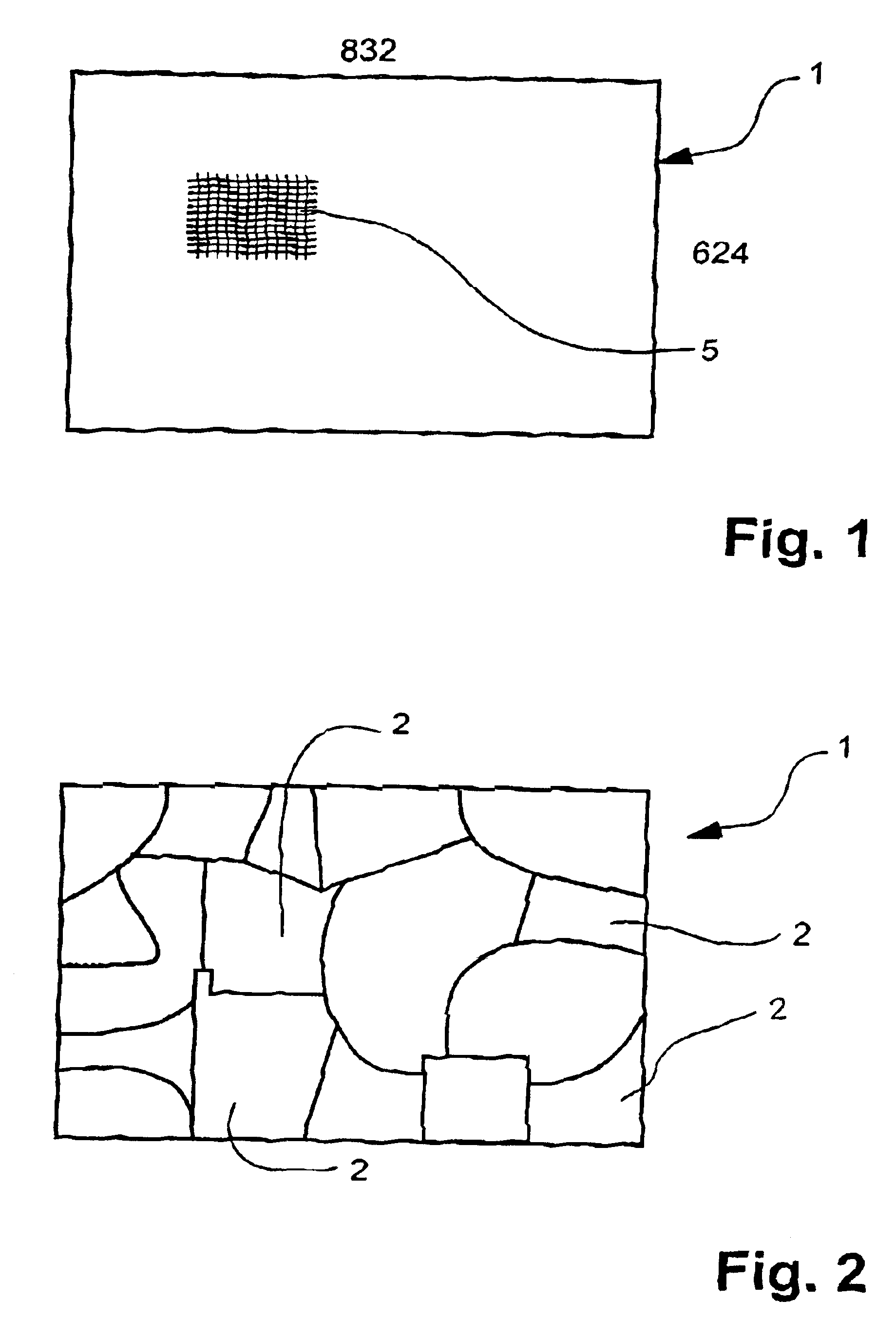
[0039]According to the present invention, rather than consider the skin colour of the image on a pixel by pixel basis as described above in relation to the prior art of Yang and Waibel, the image 1 is segmented into a number of regions. An example of such segmentation is schematically illustrated in FIG. 2 on the segmentation basis that all the pixels in each region 2 have substantially the same colour. Alternatively the image may be segmented into arbitrary regions for processing.

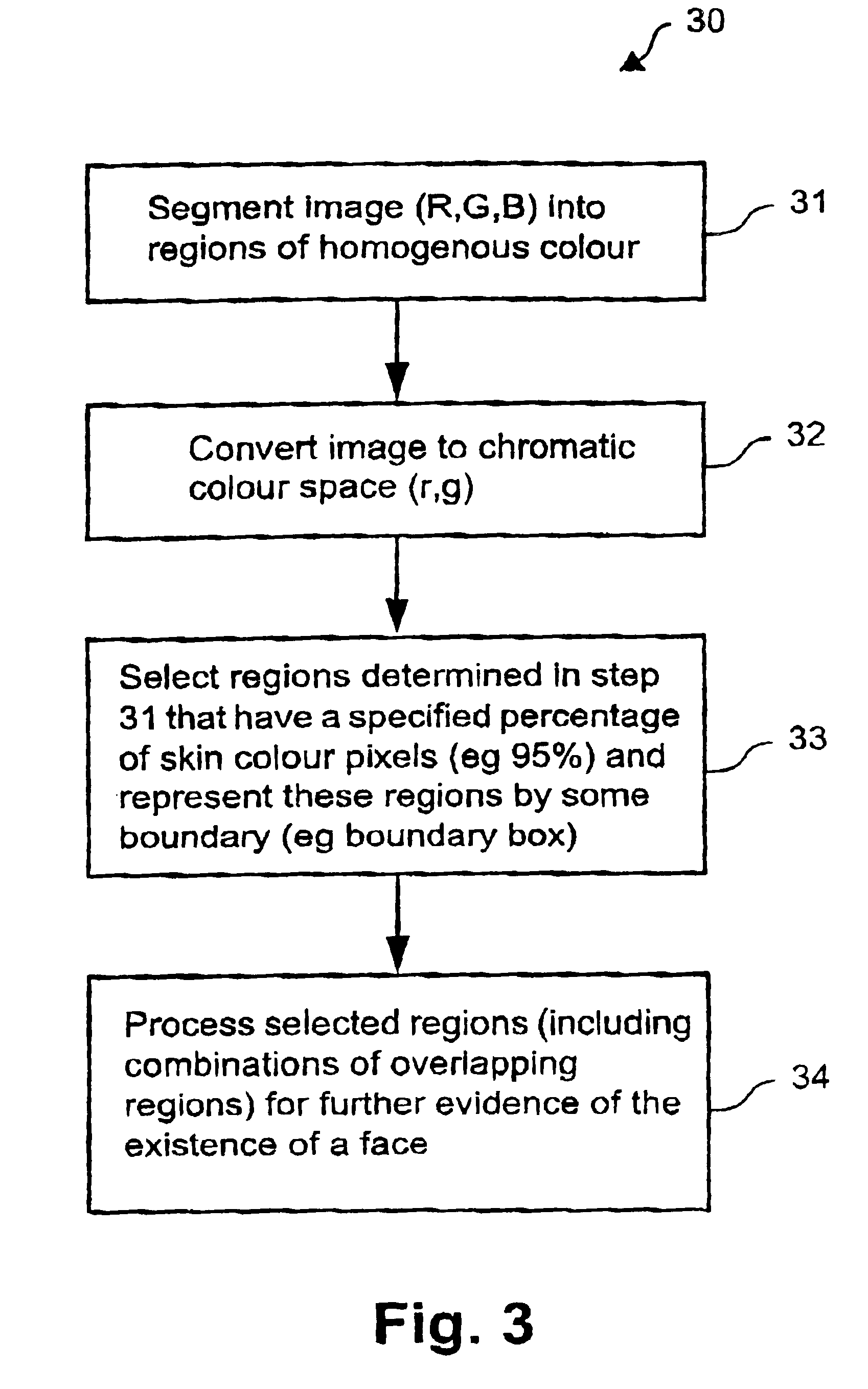
[0040]The first embodiment implements a process 30 illustrated in the flow chart of FIG. 3, in which the regional segmentation of the image is carried out at step 31. Next, the regions of the image are converted in step 32 into the chromatic colour space (as descried above). The next step 33 is to select those of the regions determined in step 31 which have a specified percentage (typically in the range 90-95%) of pixels having a skin colour. These selected regions are then conveniently represented by a bo...

second embodiment

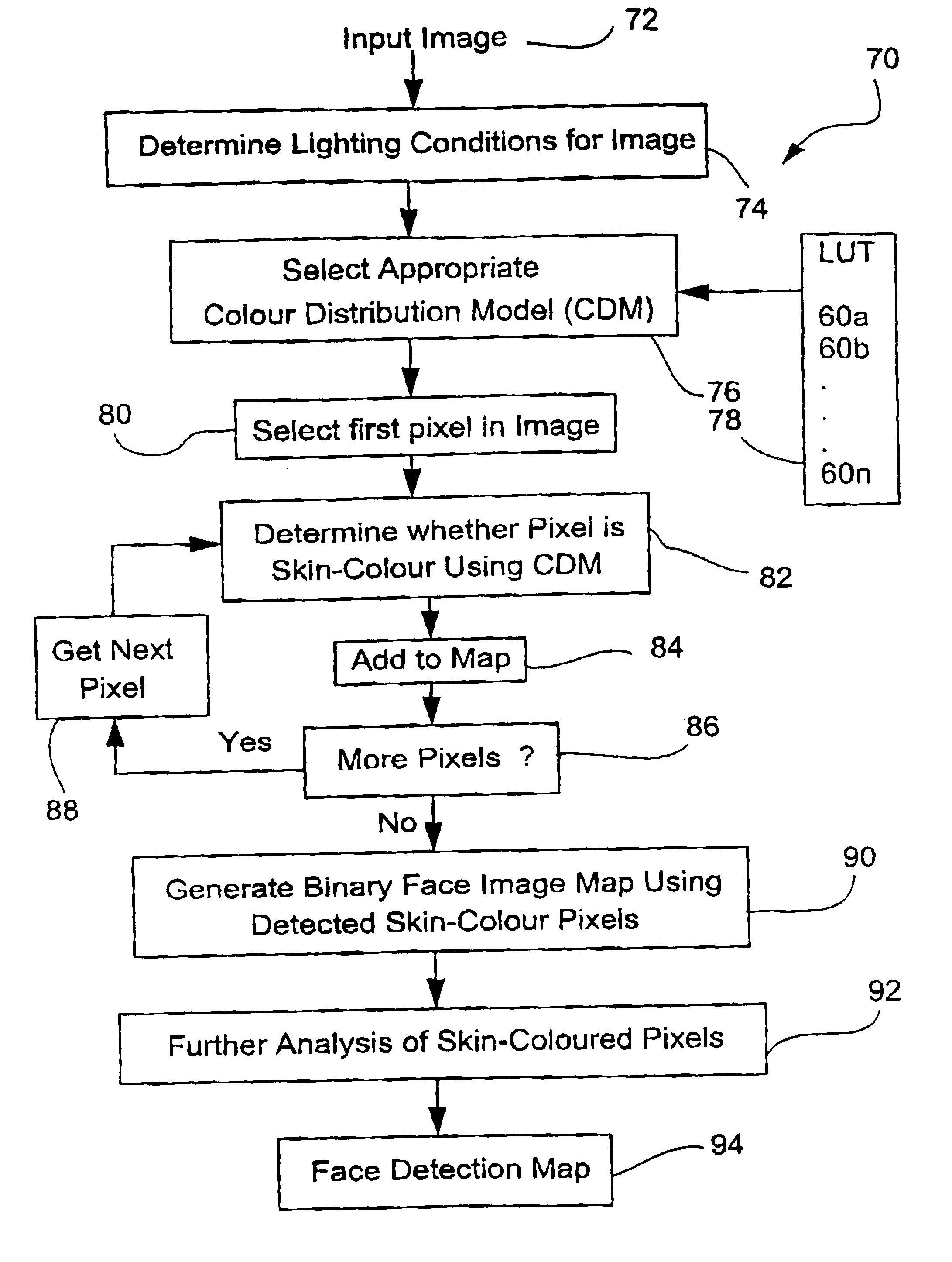
[0063]The processing 70 of an image is shown in FIG. 6. An input image is provided at step 72 and at step 74 the lighting conditions under which the image was captured are determined. Such a determination may be based on binary data obtained directly from the camera (eg. flash+indoors, no13flash+outdoors, no13flash+indoors, flash+outdoors) or corresponding meta-data provided with, or accompanying, the image, which may be encoded or otherwise communicated according to a predetermined format. Once the lighting conditions are determined, a corresponding or closest CDM is selected from a bank of look-up tables 78 retaining the CDM's (60a . . . 60n) previously determined. At step 80, a fire pixel of the input image 72 is selected and at step 82 is tested to see if th (GB or YUV) colour of the pixel is contained in the selected CDM (60a . . . 60n).

[0064]The steps shown in FIG. 6 following the comparison of step 82 depend upon the manner in which the CDM's are stored. In a preferred imple...


PUM


Abstract

A method and apparatus for the detection of faces in a digital image captured under a variety of lighting conditions are provided. Rather than subjecting an entire image to computationally intensive face detection analysis, the image is subjected to computationally simply analysis to identify candidate pixels likely to be of skin colour. Only those pixels having such color are subject to computationally intensive face detection analysis. The pixels are selected by first selecting a color distribution model based on an image capture condition provided with the color digial image. Then, the color of the pixels is tested using the distribution model to determine those pixels having predominantly skin color. Preferably, the distribution model is selected from among a number of different distribution models with each of the distribution models associated with a different set of lighting conditions. In this way, a face detection process may accommodate a variety of lighting conditions associated with the capture of an image using a computationally simple analysis.

Description

CROSS REFERENCE TO RELATED APPLICATION[0001]This application is a continuation-in-part of application Ser. No. 09 / 326,561 filed Jun. 7, 1999 now U.S. Pat. No. 6,661,907.BACKGROUND ART[0002]Colour digital images are increasingly being stored in multi-media databases, and utilised in various computer applications. En many such applications it is desirable to be able to detect the location of a face in a visual image as one step in a multi-step process. The multi-step process can include content-based image retrieval, personal identification or verification for use with automatic teller machines or security cameras, or automated interaction between humans and computational devices.[0003]Various prior art face detection methods are known including eigenfaces, neural networks, clustering, feature identification and skin colour techniques. Each of these techniques has its strengths and weaknesses, however, one feature which they have in common is that they are computationally intensive an...

Claims


Application Information

Patent Timeline
IPC IPC(8): G06K9/00G06T7/00
CPCG06K9/00234G06V40/162
Inventor HO, EDWINLENNON, ALISON JOANBRADLEY, ANDREW PETER
Owner CANON KK
Why Eureka
Try Eureka