Surface illuminator using point light source

a technology of surface illuminator and point light source, which is applied in the direction of waveguides, lighting and heating apparatus, instruments, etc., can solve the problems of insufficient surface illuminators in the prior art to produce and the difficulty of producing a uniform surface brightness or luminance of light guide plates

Inactive Publication Date: 2007-05-15
IIMURA KEIJI
View PDF12 Cites 77 Cited by
  • Summary
  • Abstract
  • Description
  • Claims
  • Application Information

AI Technical Summary

Problems solved by technology

These conventional surface illuminators have such drawback that it is difficult to produce a uniform surface brightness or luminance of the light guide plate along entire areas of that surface lighting surface i.e. light output surface, since the point-like light source, especially LED has a very narrow spread angle or directivity and resultantly the surface lighting surface has not only bright areas but also dark areas, i.e. uneven surface brightness or luminance along or over its lighting surface area.
However, the surface illuminators in these prior arts are not yet sufficient to produce a uniform surface brightness or luminance along or over an entire area of a surface lighting or light emitting surface of the surface lighting light guide member.

Method used


Image

  • Surface illuminator using point light source
  • Surface illuminator using point light source
  • Surface illuminator using point light source

Examples


tenth embodiment (embodiment

[0380]Reference is made to FIG. 35 through FIG. 38 showing a tenth embodiment of the present invention, in which FIG. 35 is a schematic exploded top view showing the tenth embodiment of the present invention, showing a modification of the reflector shown in e.g. FIG. 1 in the first embodiment and FIG. 36 through FIG. 38 is schematic top views showing three types of configuration of the tenth embodiment.

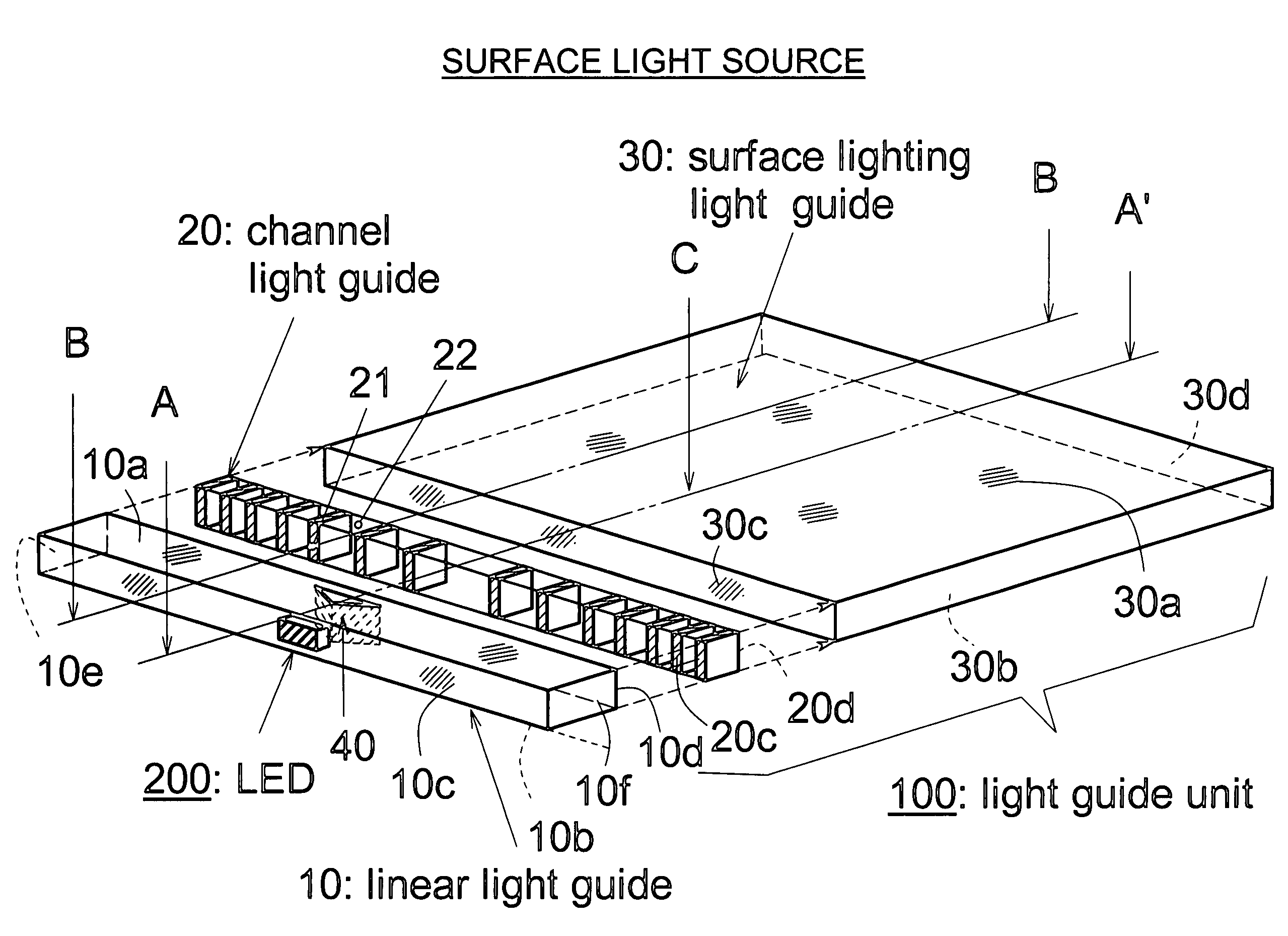
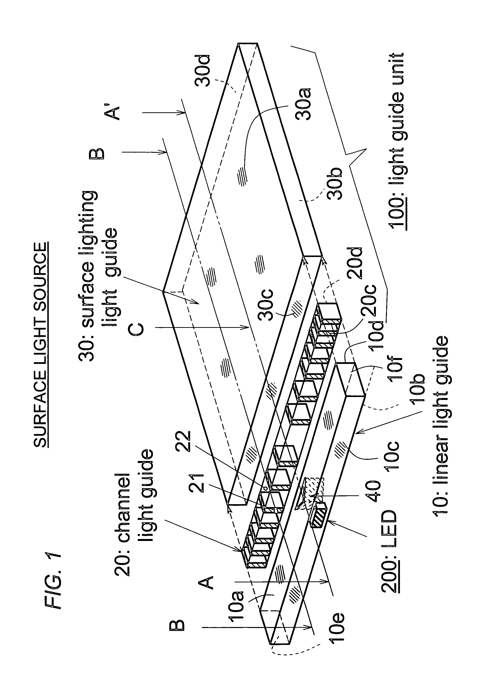
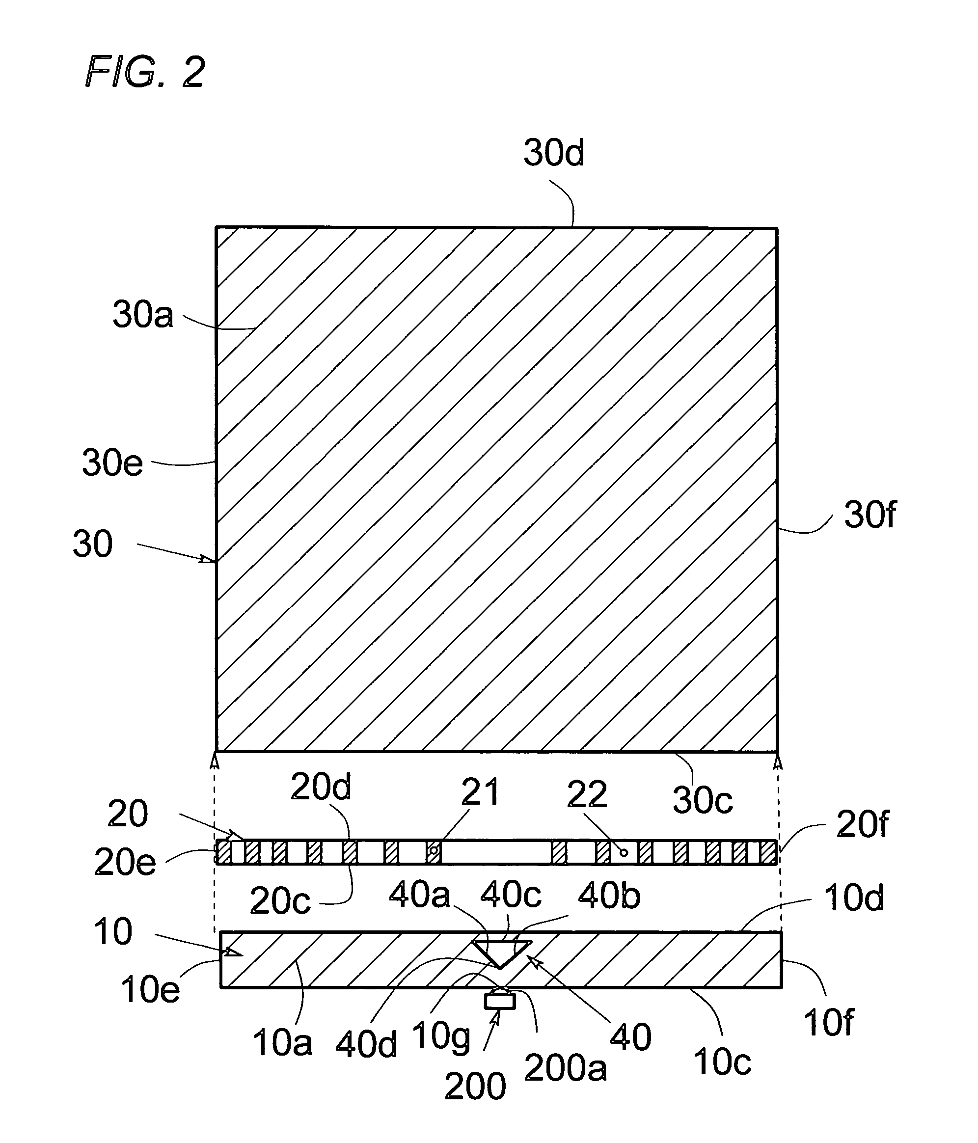
[0381]In FIG. 35, a surface illuminator is composed of a substantially transparent light guide unit 123 and LED / LEDs 200, in which the light guide unit 123 is composed of a linear light guide member 13, a channel light guide member 20 having optical channel elements i.e. solid cores 21 and air interposers 22 i.e. air clads and a surface lighting light guide member 30.

[0382]The linear light guide member 13 is composed of opposed major surfaces, opposed rear and front side surfaces 13c and 13d and opposed end surfaces 13e and 13f.

[0383]The rear side surface 13d has opposed reflecting s...

eleventh embodiment (embodiment

[0395]Reference is made to FIG. 39 through FIG. 42 showing an eleventh embodiment of the present invention, in which FIG. 39 is a schematic exploded top view and FIG. 40, FIG. 41 and FIG. 42 are schematic top views showing three types of light guide units.

[0396]In FIG. 39, a surface illuminator of the eleventh embodiment is composed of a substantially transparent light guide unit 124 and a LED 200, in which the light guide unit 124 is composed of a linear light guide member 13, a channel light guide member 26 having optical channel elements (i.e. solid cores) 27 and air interposers (i.e. air clads) 28 and a surface lighting light guide member 30.

[0397]The linear light guide member 13 is composed of at least opposed major surfaces, opposed rear and front surfaces 13c and 13d and opposed end surfaces 13e and 13f.

[0398]The front side surface 13d includes opposed reflecting side surfaces 44a and 44b thereon near a center thereof, in which the opposed reflecting side surfaces 44a and 44...

twelfth embodiment (embodiment

[0438]Reference is made to FIG. 49, FIG. 50A and FIG. 50B showing a twelfth embodiment of the present invention, in which FIG. 49 is a schematic exploded perspective view, FIG. 50A is a schematic top view showing a linear light guide member 14 and FIG. 50B is a schematic cross sectional view showing the linear light guide member 14 taken along the line D—D in FIG. 49.

[0439]As shown in FIG. 49, a surface illuminator of this embodiment is composed of a light guide unit 131 having a linear light guide member 14, a channel light guide member 20 and a surface lighting light guide member 30, and a LED 200.

[0440]The channel light guide member 20 is composed of a plurality of optical channel elements i.e. solid cores 21 and a plurality of air interposers i.e. air clads 22 disposed therebetween, in which the optical channel elements 21 form a linear array, as described in detail hereinbefore.

[0441]The channel light guide member 20 is composed of a plurality of optical channel elements i.e. s...


PUM


Abstract

The disclosed apparatus is a surface illuminator i.e. surface light source typically used in lighting for liquid crystal displays (LCDs). The surface illuminator using point light source may comprise a first light guide member for a surface lighting having a first light exiting surface and a first light entering surface; a second light guide member for a light distribution having a second light exiting surface and a second light entering surface; at least one point light source (LED) optically communicated with the second light entering surface; a channel light guide member having a fiber optic channel array having a plurality of light guiding portions optically isolated one another; and wherein the channel light guide member is disposed between the first light guide member and the second light guide member. The second light guide member may be an elongated light guide member having a linear or nonlinear elongated member.

Description

CROSS-REFERENCE TO RELATED APPLICATIONS[0001]This application claims the benefit of the prior foreign application: Japanese Patent Application No. 2004-176193 filed on Jun. 14, 2004 in the Japan Patent Office and the entire disclosure of which is incorporated herein by reference in this application.BACKGROUND OF THE INVENTION[0002]1. Field of the Invention[0003]The present invention relates to a surface illuminator (i.e. a surface light source, a surface lighting device, a planer or plane light source, a flat light source, an edge light source, a side light source) that uses a plate-like or panel-like light guide (i.e. light guiding member, optical waveguide, optical or light conducting member) and at least one point light source (i.e. a point-like or dot-like light source), such as a light emitting diode / diodes (LED / LEDs).[0004]The present invention further relates to the surface illuminator typically for use in a backlighting or front-lighting of a liquid crystal display (LCD).[00...

Claims


Application Information

Patent Timeline
Patent Type & Authority Patents(United States)
IPC IPC(8): G02B6/10F21V7/04F21V8/00F21Y101/02G02B6/00H01L33/60
CPCG02B6/0018G02B6/0028G02B6/0036G02B6/0043G02B6/0048G02B6/0061G02B6/0068Y10S385/901
Inventor IIMURA, KEIJI
Owner IIMURA KEIJI
Why Eureka
Try Eureka