Method and apparatus for recording and playing back monitored video data

a video data and video recording technology, applied in the field of methods and apparatuses for recording and playing back video data, can solve the problems of large moment, difficult control of continuous feeding of tape, and inability to record audio signals in audio tracks

Inactive Publication Date: 2007-05-15
HITACHI INFORMATION & CONTROL SOLUTIONS LTD
View PDF4 Cites 7 Cited by
  • Summary
  • Abstract
  • Description
  • Claims
  • Application Information

AI Technical Summary

Benefits of technology

[0010]It is an object of the present invention to provide a method and an apparatus for recording and playing back monitored video data, which can store video data on a magnetic tape for a period enough to be used for monitoring and preventing crimes, etc. In addition, in the apparatus, it is no need to record video data while the recording head is put in contact with the magnetic tape for a long time and while the recording head is moved, without special mechanisms for intermittent feeding, etc. In other words, a general home VTR can also be used to store video data on a magnetic tape for a period enough to monitor and prevent crimes, etc.
[0011]It is another object of the present invention to solve the above-mentioned problems of conventional time lapse VTR and provide an apparatus for recording and playing back video data, which can improve its mechanical reliability and extend the life of the magnetic tape in use by reducing the operating time of the parts that will apt to wear and be damaged, without employing any high precision control means for intermittent tape feeding.
[0012]It is a further object of the present invention to provide an apparatus for recording and playing back video data, which can output good quality playback images without degrading the playback signals even in a different tape-speed mode from the recording mode.
[0015]Furthermore, the present invention provides an apparatus for recording and playing back monitored video data and storing video signals generated continuously for a long time on a magnetic tape, comprising a means of generating video signals continuously for a long time; a means of entering video signals generated by the video signal generating means continuously for a long time and compressing the video signals on the time axis so as to be output as digital signal video data; and a means of recording and playing back digital video data from the time axis compressing means on a magnetic tape, wherein the period in which the magnetic tape recording means records digital video data on the magnetic tape is shorter than the period in which the video signal generating means generates video signals continuously.

Problems solved by technology

In such a super-long time recording operation, the average tape feed speed is very slow, so that it becomes difficult to control the continuous feeding of the tape.
To avoid this problem, the tape is fed intermittently in most cases and accordingly, it becomes impossible to record audio signals in audio tracks.
Further, since the cylinder has a large moment and takes much time until its rotation speed is stabilized, the cylinder must be rotated almost at a fixed speed continuously during the recording.
Especially, in the above super-long recording mode (720-hour mode), the VTR has a disadvantage that because the cylinder is kept rotated in contact with the tape for 720 hours, the tape is damaged far more rapidly than used for a home VTR.
In the same way, because the head is in contact with the tape, the head is also worn rapidly.
The mechanisms such as the motor and belt used for making the cylinder rotate are also degraded rapidly and often damaged, since they are running for a long time respectively.
Further, conventional helical scanning VTR also has a following defect; the recording track pattern angle on the tape loaded is decided by both the rotation speed of the cylinder and the feed speed of the tape, so that the track pattern recorded at the above slow speed tape feeding or the tape stops has an angle different from the normal speed tape feeding.
Therefore, when playing back the track pattern recorded in such way, a mismatching occurs between the tracing angle of the head and the angle of the track pattern, causing the SIN (signal-noise ratio) to be degraded in a part of the playback signals, with the resultant of lowering the quality of output pictures significantly.

Method used


Image

  • Method and apparatus for recording and playing back monitored video data
  • Method and apparatus for recording and playing back monitored video data
  • Method and apparatus for recording and playing back monitored video data

Examples


first embodiment

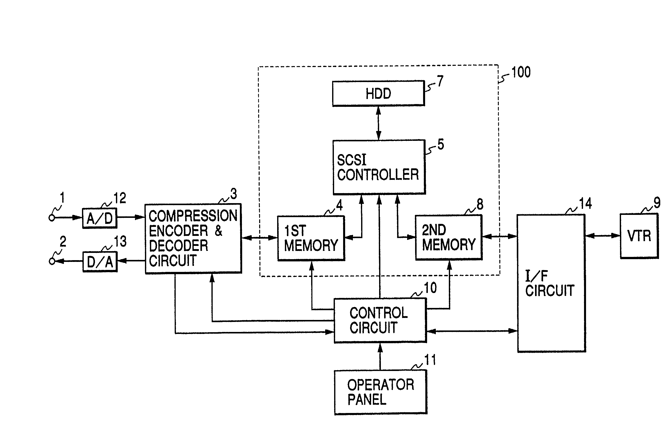
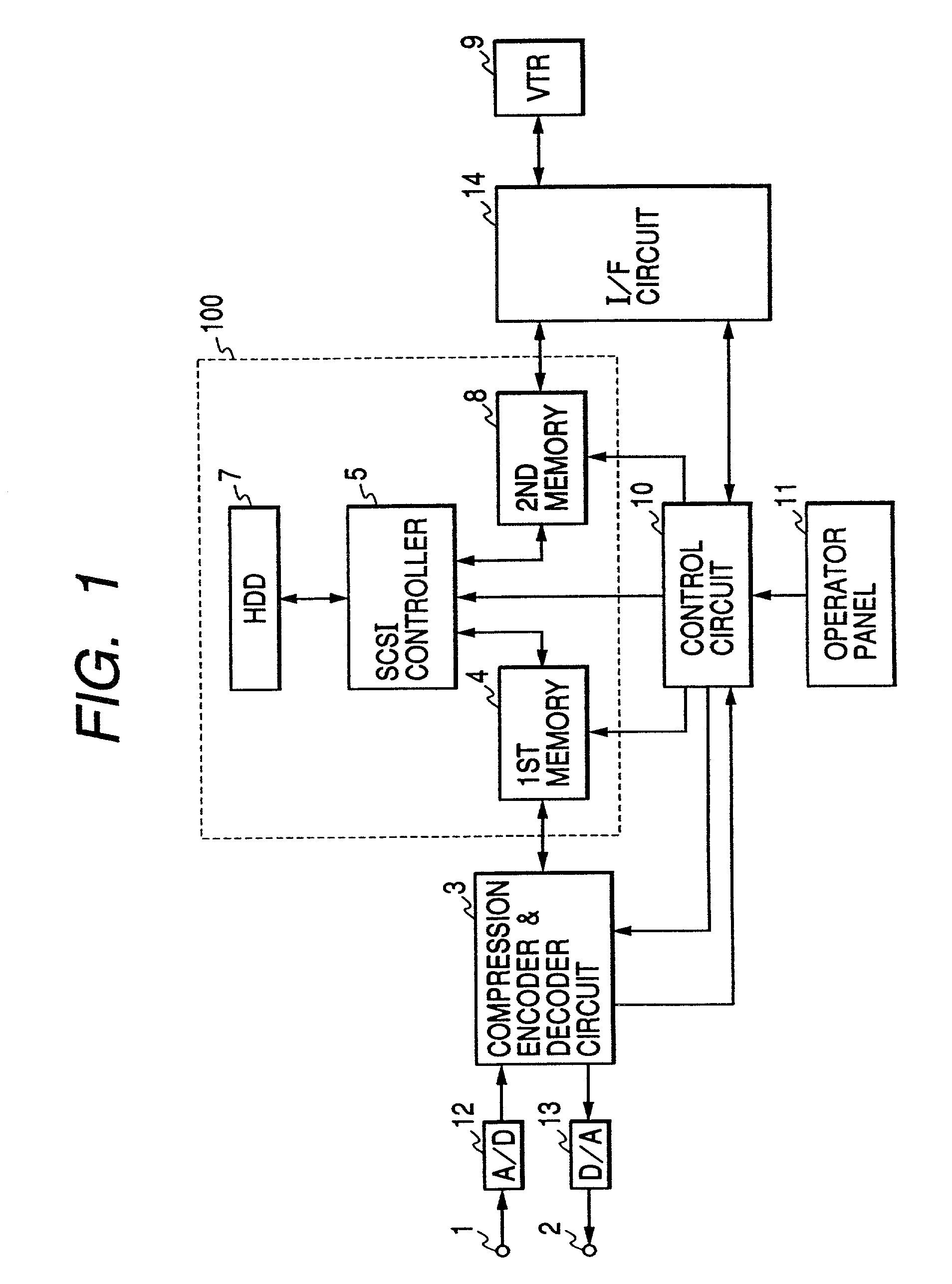
[0034]FIG. 1 is a block diagram of the recording & playback apparatus for monitored video data in the present invention. In FIG. 1, numeral 1 indicates a terminal to input video signals from a video camera (not illustrated), 2 indicates a terminal to output video signals, 3 indicates a compression encoder & decoder circuit, 4 and 8 indicate semiconductor memories (4: the first memory, 8: the second memory), 5 indicates an SCSI (Small Computer System Interface) controller, 7 indicates a hard disk unit (hereafter, to be abbreviated as HDD) provided with an SCSI interface, 9 indicates a VTR, 10 indicates a control circuit, 11 indicates an operator panel from which the operator instructs various operations, 12 indicates an A / D converter, 13 indicates a DIA converter, and 14 indicates an IEEE1394 interface circuit (hereafter, to be abbreviated as I / F circuit). Of those devices, the semiconductor memories (the first and second memories 4 and 8), the SCSI controller 5, the HDD 7 are combin...

second embodiment

[0084]Subsequently, the monitored video data recording & playback apparatus in the present invention will be explained.

[0085]In this second embodiment, the input video data time axis is thinned out to record video data at a smaller rate and enable super-long time continuous recording of video data.

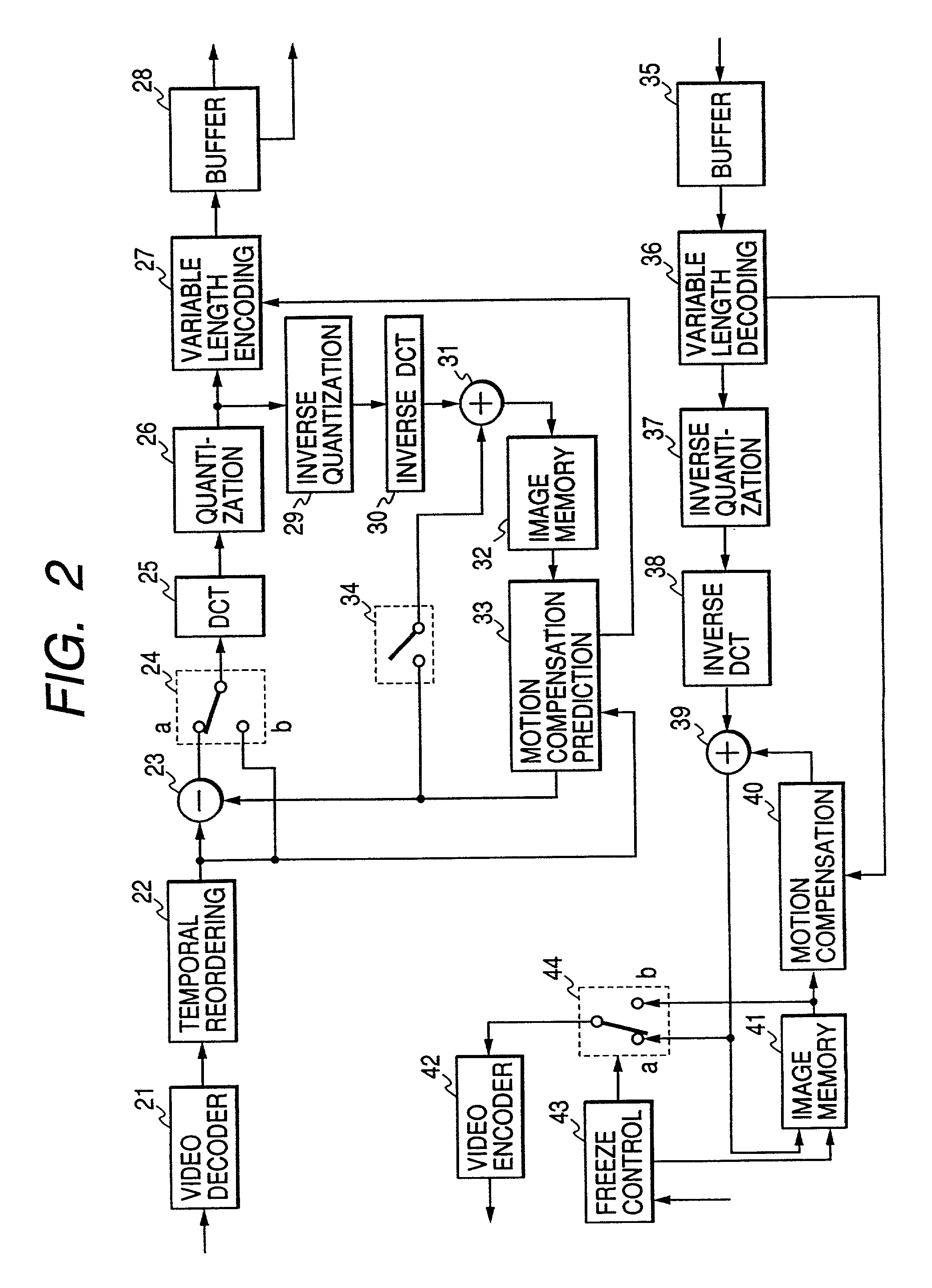
[0086]At first, FIG. 6 is a block diagram of the compression encoder & decoder circuit (refer to 3 in FIG. 1, and FIG. 2) to thin out the above time axis. This compression encoder & decoder circuit differs from the compression encoder & decoder circuit 3 shown in FIG. 2 in that a thinning-out circuit 45 is added and the speed of the compression encoding main processor (enclosed by a broken line) operation can be changed according to the mode signal from the thinning-out circuit 45. This thinning-out circuit 45 writes the frame period of video data from the decoder 21 in a memory and reads the data from the memory for a k-frame period at a reading rate of 1 / k (k=a natural number of 2 or ove...

third embodiment

[0100]In the monitored video data recording & playback apparatus in the present invention explained above, the output from the HDD 7 or 16 is never interrupted by the MRR1 signal. In other words, recording and output operations are not time-shared. Consequently, the present invention can have an advantage for using a hard disk unit whose recording or output data rate is comparatively low. In other words, when the output rate of the compression encoder & decoder circuit 3 is 1.5 M bps, the recording rate should be 1.5 M bps or over. When the input data rate of the VTR 9 is 14.1 M bps, the playback data rate should be 14.1 M bps or over. And, just like in the firs embodiment, the wear and degradation of the magnetic tape 79, the head 81 and 82, and other mechanical parts can be reduced effectively.


PUM

PropertyMeasurementUnit
recording timeaaaaaaaaaa

Abstract

A method and an apparatus for recording and playing back monitored video data for recording monitored video data generated continuously for a long time on a magnetic tape, with less S / N degradation by shortening the operation time of the VTR to suppress the degradation of the magnetic tape, recording head, and other mechanical items, wherein video signals from a video camera are converted to digital signals in an A / D converter, compressed and encoded in a compression encoder & decoder circuit, then transferred to a time axis compression circuit including the first memory, the second memory, an SCSI controller, and a hard disk unit, thereafter compressed on the time axis and recorded on the magnetic tape loaded in a D-VHS standard VTR via an I / F circuit. Compressing the video data from the compression encoder & decoder circuit on the time axis in the time axis compression circuit makes shorter the recording time of the video data on the magnetic tape than the actual recording time of the video camera, whereby the VTR is only required to record video data intermittently on the magnetic tape and that a general home VTR can be adopted as the above VTR, moreover the magnetic tape itself is prevented from damages.

Description

[0001]This application is a continuation of application Ser. No. 09 / 780,429, filed Feb. 12, 2001, now issued as U.S. Pat. No. 6,684,024, which is a continuation of application Ser. No. 09 / 015,344, filed Jan. 29, 1998, now abandoned. Each application claims the priority of Japanese application Number 9-015190, the disclosure of which is expressly incorporated by reference herein.BACKGROUND OF THE INVENTION[0002]The present invention relates to methods and apparatuses for recording and playing back video data, more particularly to a method and an apparatus for recording and playing back monitored video data, which will be suitable for recording video data for a long time for the purpose of monitoring and preventing of crimes.[0003]There is provided a prior art time lapse VTR used as a video data recording device for recording video data from, a video camera, suitable for monitoring and preventing crimes. Many of this type VTR are improved from a home VHS VTR which is very popular at p...

Claims


Application Information

Patent Timeline
Patent Type & Authority Patents(United States)
IPC IPC(8): H04N7/00G11B5/86H04N5/76H04N5/781H04N7/26H04N7/50H04N9/804
CPCH04N5/76H04N19/423H04N19/61H04N5/781H04N9/8042H04N5/765H04N5/782H04N9/8045H04N19/107H04N1/00
Inventor ONO, KOICHIKANESAKI, TAKAYUKINISHIJIMA, HIDEO
Owner HITACHI INFORMATION & CONTROL SOLUTIONS LTD
Why Eureka
Try Eureka