Compressor fuel gas conditioner

Active Publication Date: 2007-05-22
PROCESS EQUIP & SERVICE
View PDF5 Cites 21 Cited by
  • Summary
  • Abstract
  • Description
  • Claims
  • Application Information

AI Technical Summary

Benefits of technology

[0011]The present invention provides a fuel gas conditioner for a natural gas compressor which is driven by an internal combustion engine. The compressor operates to draw natural gas from the well and move it into and through a pipeline gathering and distribution system. A portion of the compressed natural gas stream that exits from the compressor is converted from a discharge line and delivered by a diverter line to a vortex tube separator. The natural gas under compression is delivered from the diverter line through a gas inlet in the vortex tube. The gas inlet injects the gas tangentially wh

Problems solved by technology

As a natural gas well begins to age, the reservoir

Method used


Image

  • Compressor fuel gas conditioner
  • Compressor fuel gas conditioner
  • Compressor fuel gas conditioner

Examples


Embodiment Construction

[0016]The embodiments discussed herein are merely illustrative of specific manners in which to make and use the invention and are not to be interpreted as limiting the scope of the instant invention.

[0017]While the invention has been described with a certain degree of particularity, it is to be noted that many modifications may be made in the details of the invention's construction and the arrangement of its components without departing from the spirit and scope of this disclosure. It is understood that the invention is not limited to the embodiments set forth herein for purposes of exemplification.

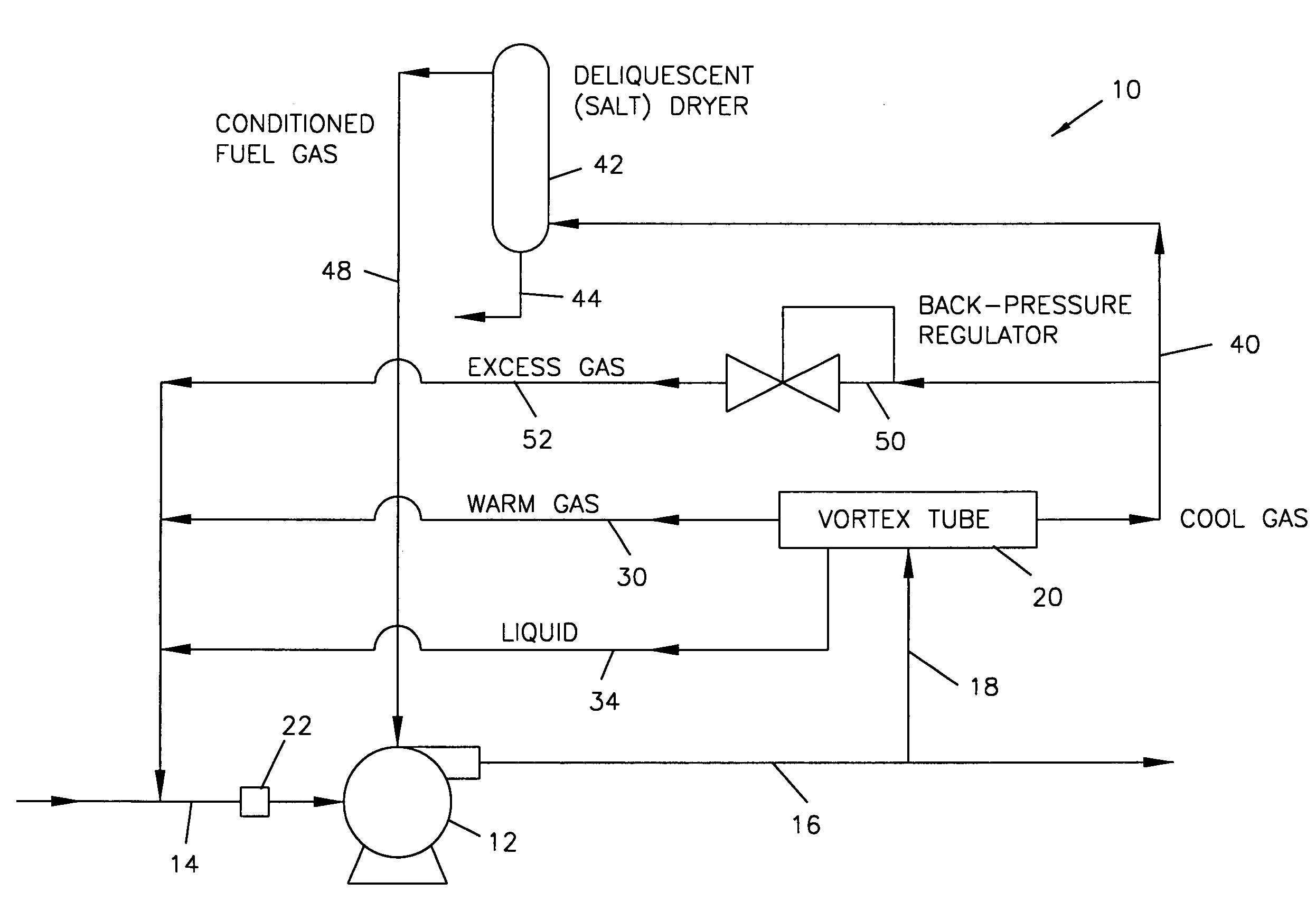
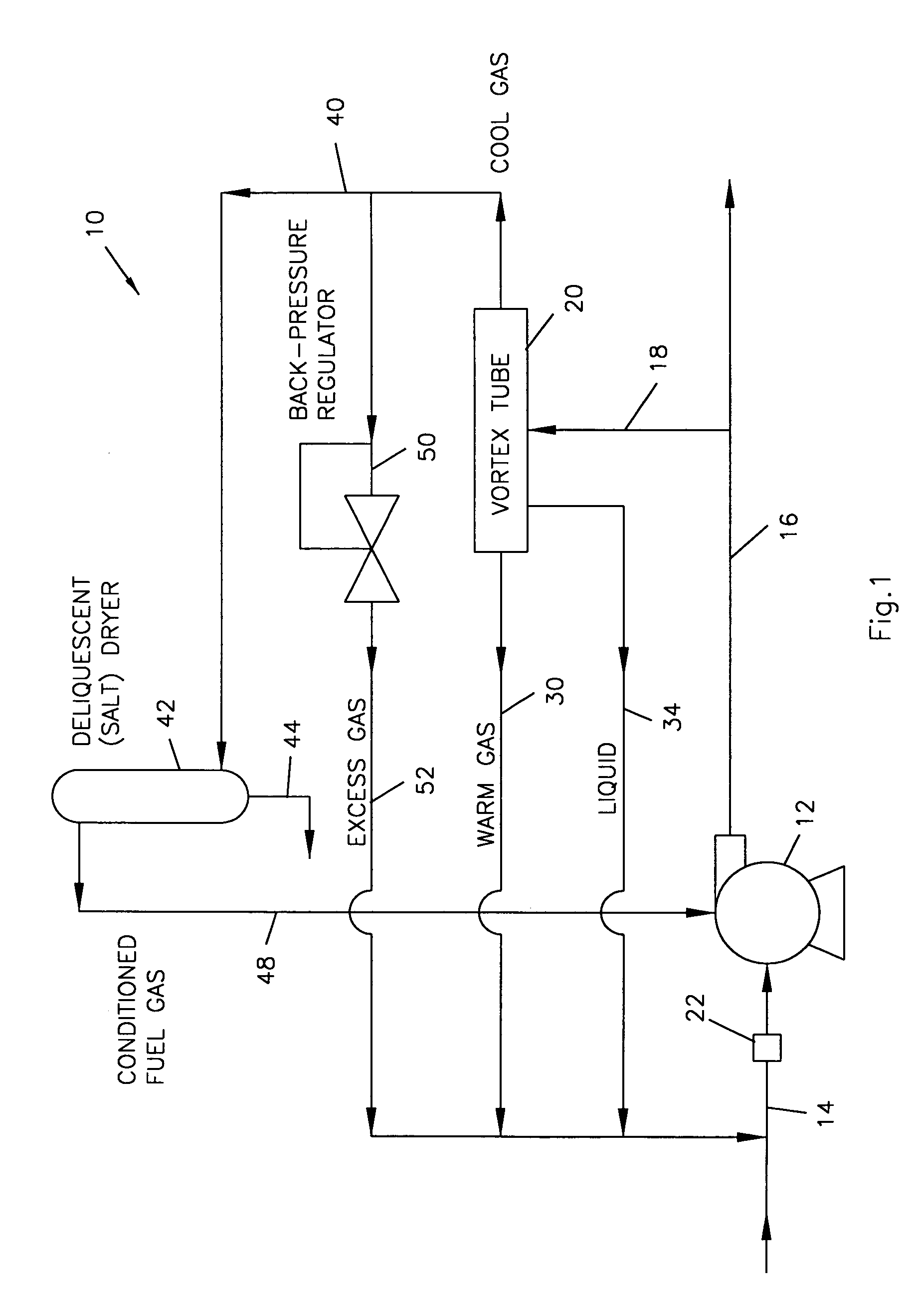
[0018]Referring to the drawings in detail, FIG. 1 illustrates a simplified schematic diagram of a compressor fuel gas conditioner system 10 constructed in accordance with the present invention. A compressor 12 driven by an internal combustion engine would be located near the natural gas well head typically at the surface (not shown). Tubing or pipe from the well would be directed into the...


PUM


Abstract

A compressor fuel gas conditioner for a natural gas well having a compressor which utilizes natural gas from the well as a fuel. The conditioner includes a vortex tube having an inlet to receive compressed natural gas from the compressor, a warm gas outlet for gas which has been heated by circular motion in the vortex tube, and a cool gas outlet for cool gas exiting the vortex tube after passing through the tube wherein the warm gas is returned to an inlet side of the compressor. A salt dryer includes a dryer inlet to receive the cool gas exiting the cool gas outlet of the vortex tube and a dryer outlet to deliver gas from the salt dryer as fuel gas to the compressor.

Description

BACKGROUND OF THE INVENTION[0001]1. Field of the Invention[0002]The present invention is directed to an apparatus and method to treat or condition natural gas for use as fuel gas for a compressor.[0003]2. Prior Art[0004]Natural gas is ordinarily gathered from subterranean wells and delivered through pipelines where it may be further treated and then distributed.[0005]At the early stages of the life of a natural gas well, reservoir downhole pressure forces natural gas through the tubing or piping in the well and up to the surface. As a natural gas well begins to age, the reservoir or downhole pressure will tend to decline over time. In some cases, it will eventually reach the same pressure as the pressure within the gas pipeline. At this point, the natural gas well will no longer flow on its own.[0006]A number of solutions to this problem have been devised. One solution is a compressor which is installed on the well, typically at the surface. The compressor will act to boost the gas ...

Claims


Application Information

Patent Timeline
IPC IPC(8): F25B9/02B01D53/24B01D59/26E21B36/00E21F1/00F04B17/00F04B35/00
CPCB01D53/26B01D53/263
Inventor RHODES, JAMES E.
Owner PROCESS EQUIP & SERVICE
Why Eureka
Try Eureka