Systems and methods for integrated energy storage and cryogenic carbon capture

a technology of energy storage and carbon capture, applied in the direction of machines/engines, lighting and heating apparatus, separation processes, etc., can solve the problems of not being able to store and recover energy, and achieve the effects of reducing parasitic load, effective grid management, and energy-efficient carbon captur

Active Publication Date: 2013-06-06
U S BANK TRUST CO NAT ASSOC
View PDF4 Cites 30 Cited by
  • Summary
  • Abstract
  • Description
  • Claims
  • Application Information

AI Technical Summary

Benefits of technology

[0017]The systems and methods described herein integrate energy storage with cryogenic carbon capture (CCC), providing effective grid management and energy-efficient carbon capture capabilities to power plants. The stored energy decreases the parasitic load created by the carbon capture process during peak demand periods. Some stored refrigerants can subsequently be combusted in turbines or other systems to further increase the output of the plant during carbon capture. The CCC process recovers most of this cooling from the cold products to cool the incoming stream, greatly decreasing the required cooling and increasing the process efficiency. CCC also involves desublimating heat exchangers that operate at steady state, avoiding the inefficiencies of cycling temperatures.

Problems solved by technology

The power generated by combustion of the refrigerant at the end of its cycle benefits the power plant in that it will be generated during times of peak energy demand, but it is not stored and recovered energy.

Method used


Image

  • Systems and methods for integrated energy storage and cryogenic carbon capture
  • Systems and methods for integrated energy storage and cryogenic carbon capture
  • Systems and methods for integrated energy storage and cryogenic carbon capture

Examples


Embodiment Construction

I. Introduction

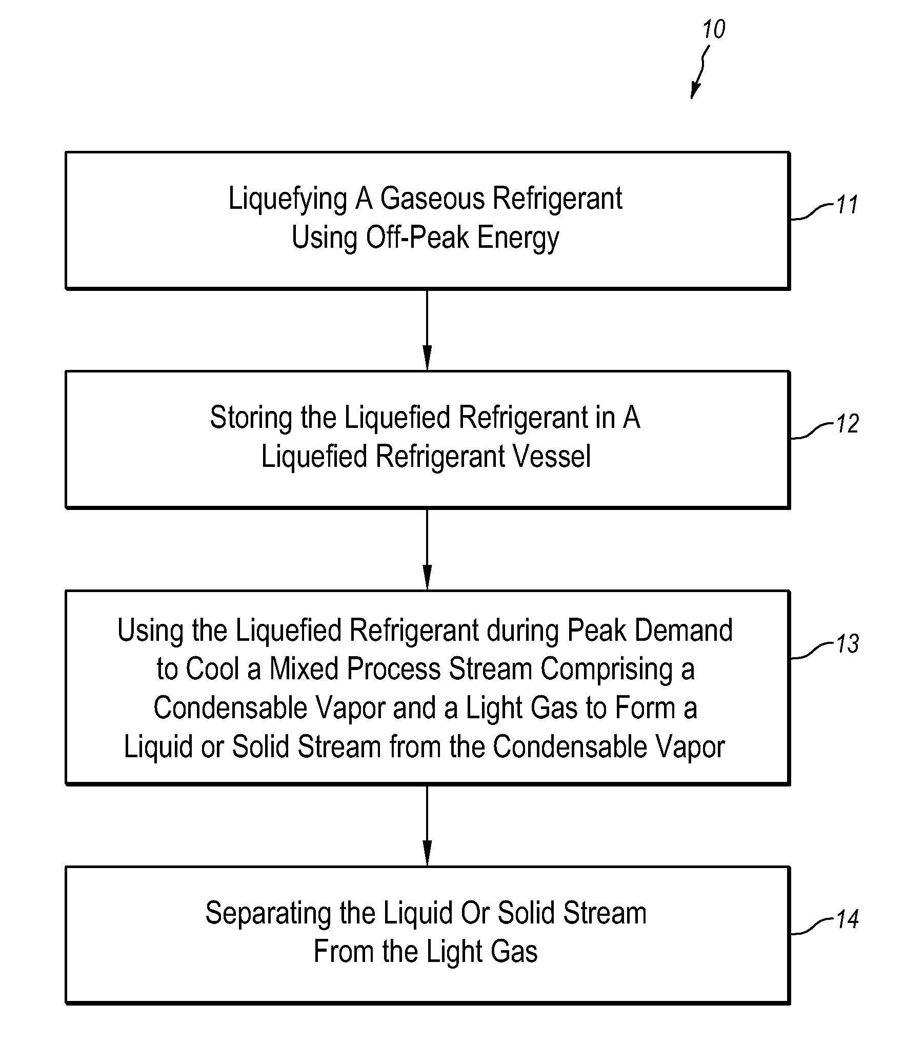
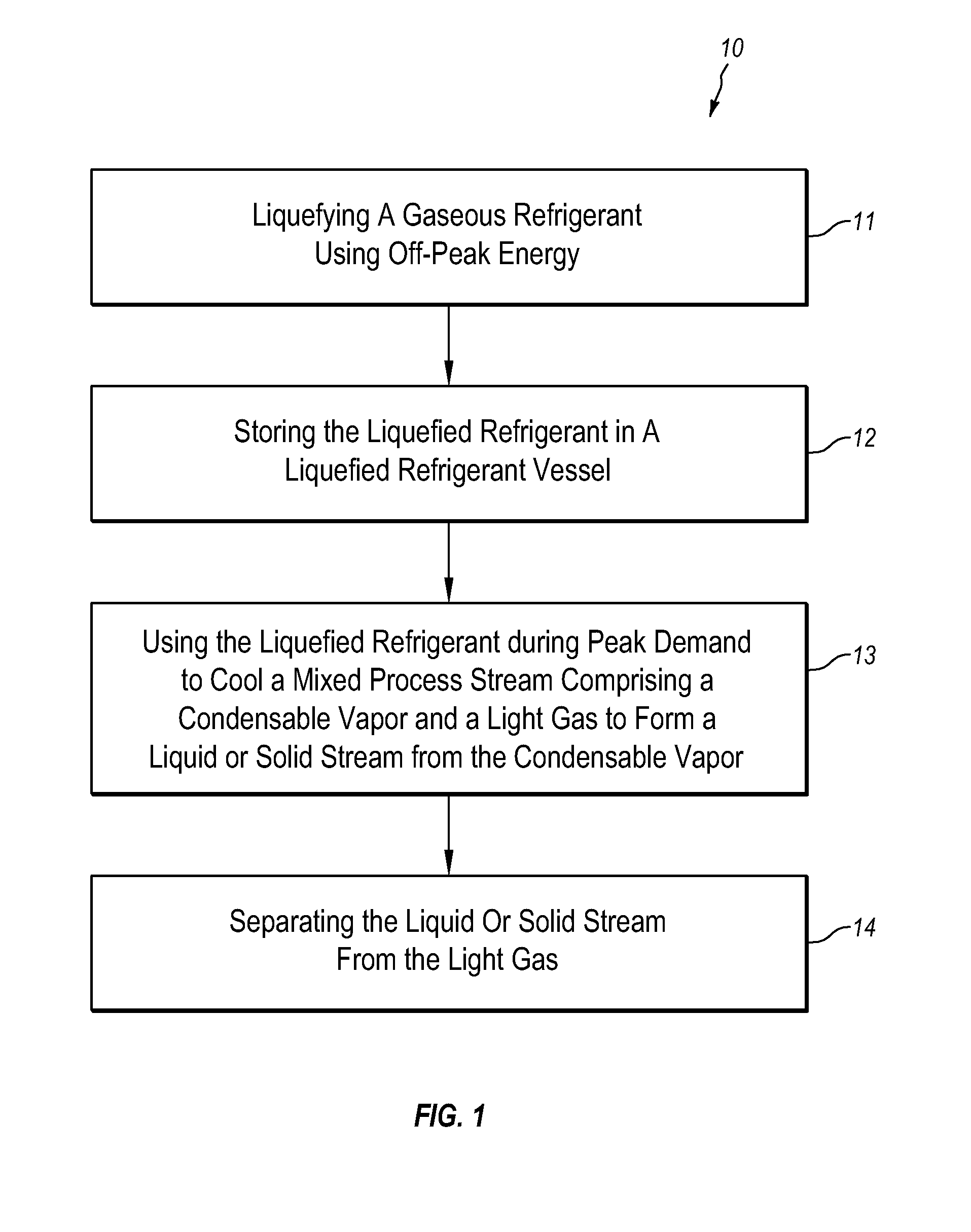
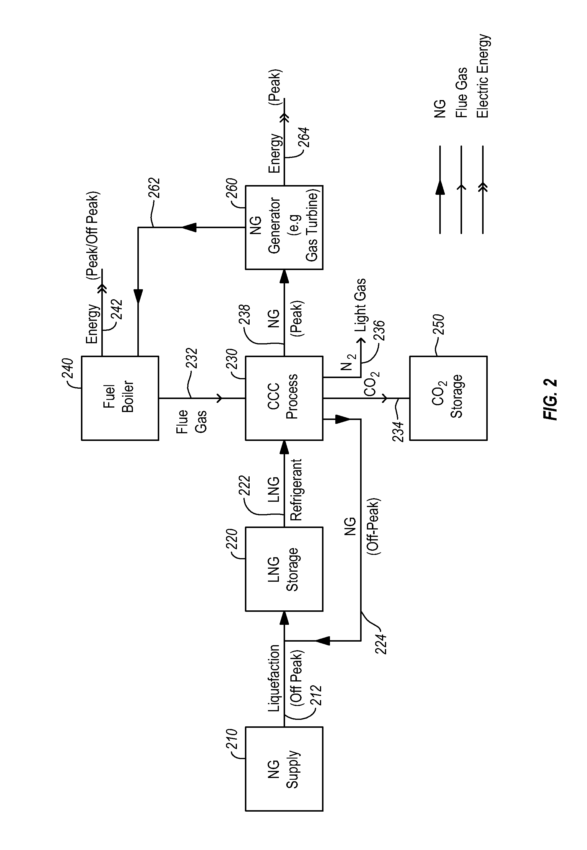
[0052]“Peak demand” as used in this document refers to times when energy demand is relatively high, as well as when energy supply is relatively low. In a power system with stable power output, such as a system powered by coal-based power plants, peak demand typically corresponds in hours of high energy demand. In a power system with intermittent power generation, such as a wind or solar power system, peak demand corresponds to times of low energy output, as well as high energy demand. Conversely, “off-peak demand” refers to times when energy demand is relatively low or when energy supply is relatively high.

[0053]The terms “peak hours”, “peak times” and “peak demand” are used interchangeably herein, unless otherwise specified.

[0054]The integrated processes of the invention store energy efficiently and change load rapidly over a significant fraction of the power capacity. The energy storage option can reduce peak load parasitic losses by shifting loads to off-peak or ch...


PUM


Abstract

The systems and methods integrate energy storage with cryogenic carbon capture, providing effective grid management and energy-efficient carbon capture capabilities to power plants. The systems store energy during off-peak demand by using off-peak energy to compress natural gas to form liquefied natural gas (LNG) and storing the LNG for use as a refrigerant. The systems use the stored LNG as a refrigerant in a cryogenic carbon capture (CCC) process to isolate carbon dioxide from light gases in a flue gas. The systems supply energy during peak demand by burning the natural gas warmed by the CCC process to generate power.

Description

CROSS REFERENCE TO RELATED APPLICATIONS[0001]The present application claims the benefit of U.S. Provisional Patent Application Ser. 61 / 627,998, filed Oct. 22, 2011, titled “Integrated Carbon Capture and Energy Storage,” which is hereby incorporated herein by reference.BACKGROUND[0002]1. The Field of the Invention[0003]The present invention relates to systems and methods that integrate energy storage and cryogenic carbon capture. More specifically, the invention provides means to store and manage energy generated by power plants or other grid-connected sources and use the stored energy in cryogenic processes to capture carbon dioxide and other condensable vapors from light gases.[0004]2. The Related Technology[0005]The separation of carbon dioxide from other light gases or liquids such as flue gas, nitrogen or methane is important for achieving carbon dioxide sequestration. Process gas (flue gas) from a conventional power station typically includes from about 4% (vol.) to about 16% (...

Claims


Application Information

Patent Timeline
Patent Type & Authority Applications(United States)
IPC IPC(8): F25J1/00
CPCF25J3/067B01D2257/504F25J1/0052F25J1/0208F25J1/023F25J1/0236F25J2205/20F25J2210/62F25J2210/70F25J2220/80F25J2220/82F25J2220/84F25J2235/80F25J2240/70F25J2240/82F25J2270/42F25J2270/58F25J2270/60F25J2270/904F25J2280/02F25J2290/80F25J1/0251F01K1/08F01K25/10F25J1/0022F02C6/14F05D2260/61F05D2260/42Y02C10/12B01D53/002F25J1/0045Y02C20/40
Inventor BAXTER, LARRY L.
Owner U S BANK TRUST CO NAT ASSOC
Why Eureka
Try Eureka