
Height-adjustable cordless brake

Inactive Publication Date: 2007-05-22
RANDOM PRODS TRUST +1
View PDF15 Cites 76 Cited by
  • Summary
  • Abstract
  • Description
  • Claims
  • Application Information

AI Technical Summary

Benefits of technology

[0003]Many persons, by reason of age or disability have difficulty in walking without a walking aid. Wheeled walkers or rollators are widely used by many such persons to assist in mobility. A wheeled walker typically has a frame mounted on four wheels and a pair of rearwardly extending handlebars, which the user can grip for support while walking. The user positions himself between the handlebars behind the walker, and pushes the walker forward. The wheels permit the user to roll the walker smoothly over the ground, thereby avoiding the laborious action of picking up and moving a non-wheeled walker in step-by-step fashion. The handle bars can be fitted with brake levers that when squeezed by the user, actuate some form of wheel braking mechanism.
[0012]Thus, there remains a need for a walking aid that offers all of the functionality of a conventional wheeled walker and can be readily converted for use as a transport chair.

Problems solved by technology

While the provision of a seat to permit the user to rest is a useful feature, it often occurs that the user is too tired to continue walking and requires the assistance of a caregiver to continue travel.
Conventional wheeled walkers are not adapted to support a seated user and be pushed by a caregiver.
In particular, because the user is seated in a rearward facing position between the handlebars, there is very little space between the user and the caregiver, making it difficult for the caregiver to take walking steps without interfering with the feet of the user.
Moreover, there is no dedicated means on conventional walkers to support the feet of the user while in the sitting position with the result that the feet are usually dragged across the ground or propped up on a frame member in an unnatural position.
While the user or the caregiver can push the apparatus from behind as a conventional walker or transport chair, in order to assume the seated position, the user must walk around to the front of the apparatus, which manoeuvre can be difficult for a physically challenged person.
While the design disclosed in U.S. Pat. No. 5,605,345 offers significant advantage, it is not well adapted for use as a walker.
Because it is based on a conventional wheelchair design, it is heavy and bulky, making it difficult to manoeuvre in confined locations.
Furthermore, the bi-directional seating arrangement uses a frame mounted link arrangement, which cannot be practicably adapted to a light walker design.
Because the seat back is pivoted to the seat base, the vertical rise of the seat back is limited and accordingly offers only lower back support.
Furthermore, when positioned in the walker mode, the seat back obscures the user's view of the ground directly in front of the walker.
However, cable type braking mechanisms have a number of deficiencies.
Moreover, because the cables are routed from the brake handle actuator to the wheels outside of the frame and require some slack to accommodate height adjustability, the resulting loop or bight in the cable is prone to catching or snagging on other objects, a deficiency which is particularly problematic in the case of a folding style walker that is transported in the trunk of a car.
Unfortunately, the solid rod linkage prevents a pin, bolt or screw from passing through both the telescoping parts of the height-adjustable handlebars, which would normally provide a secure, but adjustable means for locking the telescoping parts together.
Unfortunately, the Malmström device relies on a single friction screw, which extends through the outer telescoping parts of the handle bars into frictional engagement with the inner telescoping brake rods, to hold the two telescoping parts of the handlebar and the two telescoping parts of the brake rod together.
Frequent tightening and loosening by elderly or otherwise disabled users make this type of system susceptible to accidental slippage, and therefore unacceptably dangerous.

Method used


Image

  • Height-adjustable cordless brake
  • Height-adjustable cordless brake
  • Height-adjustable cordless brake

Examples


Embodiment Construction

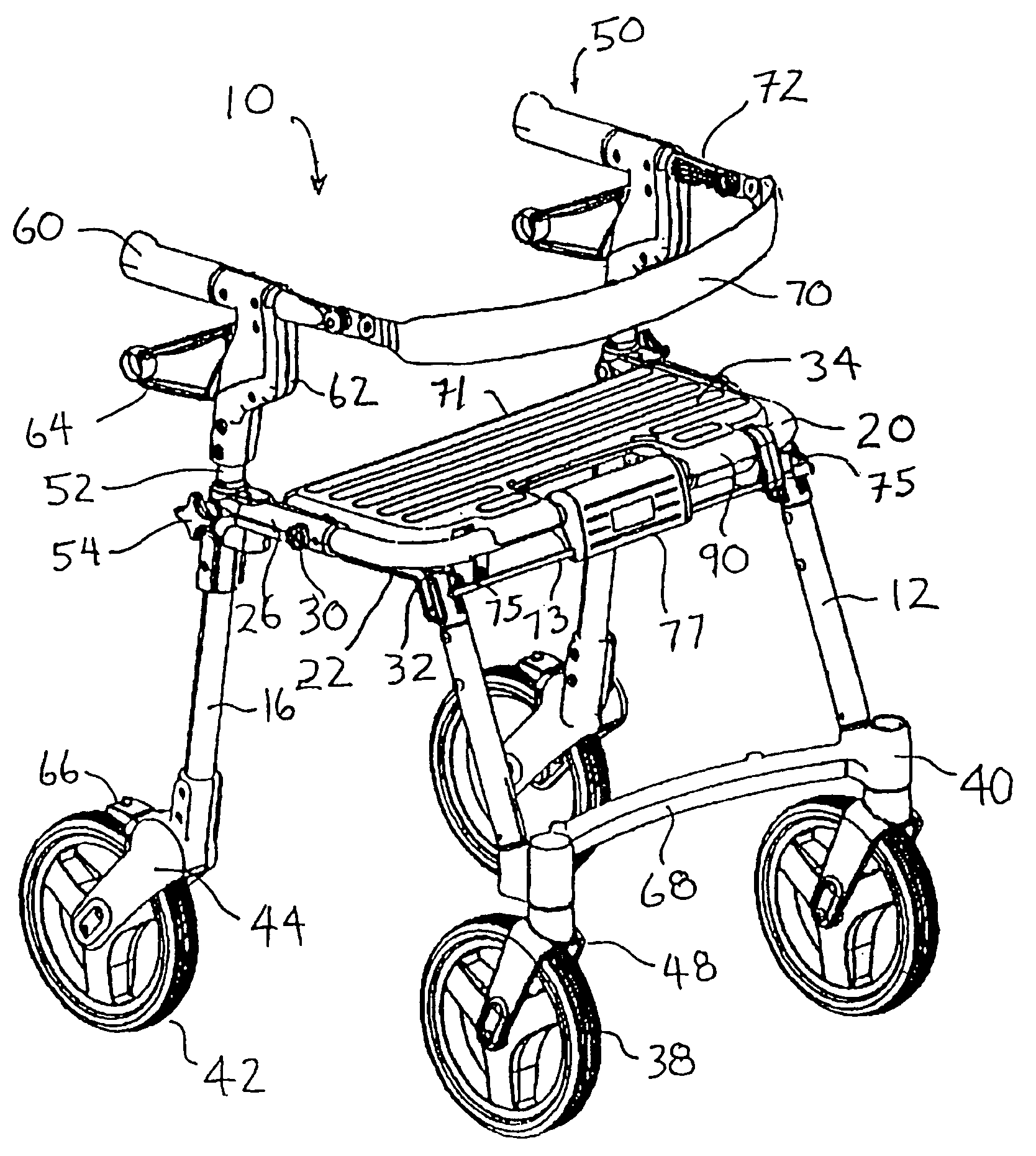
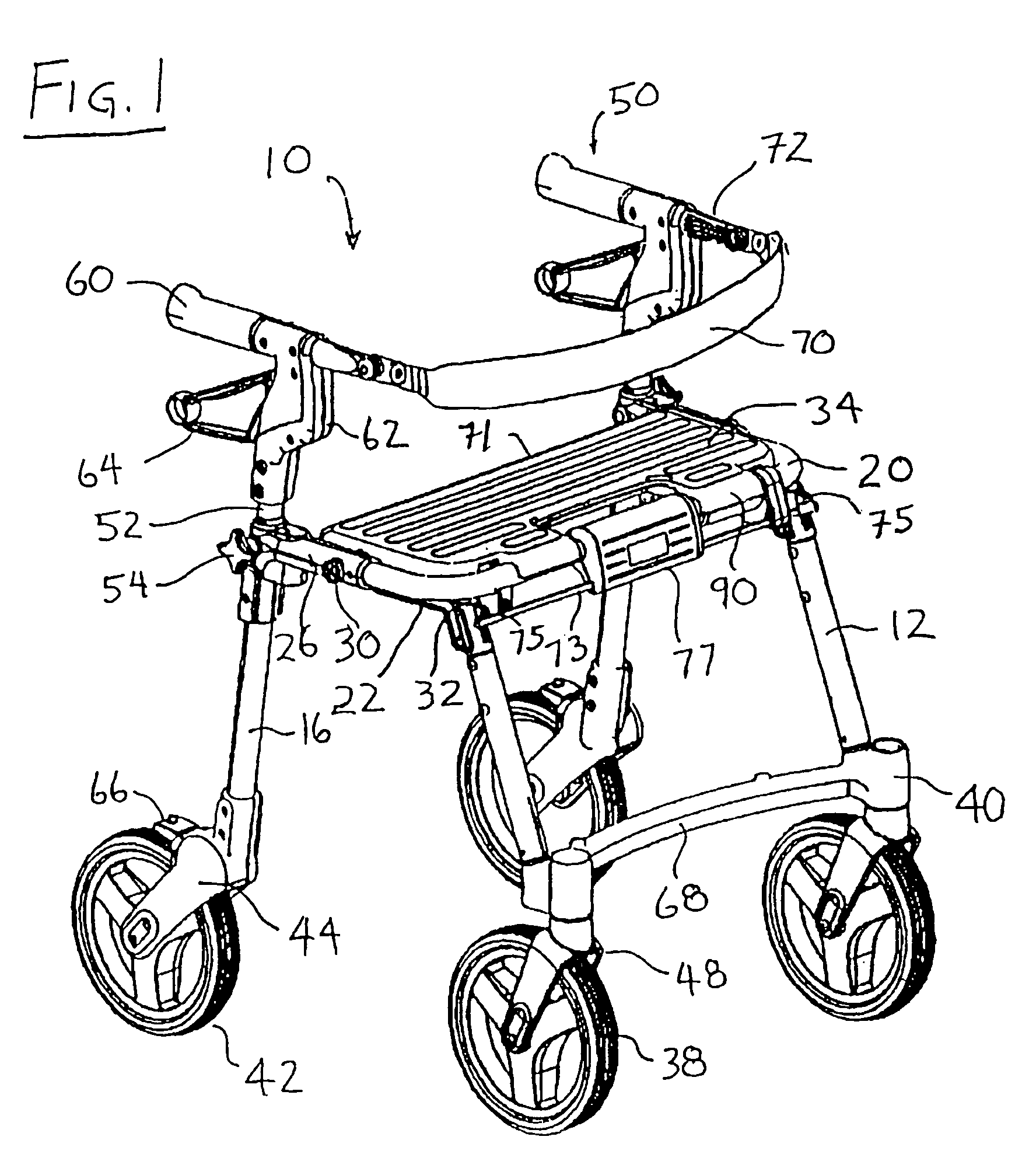
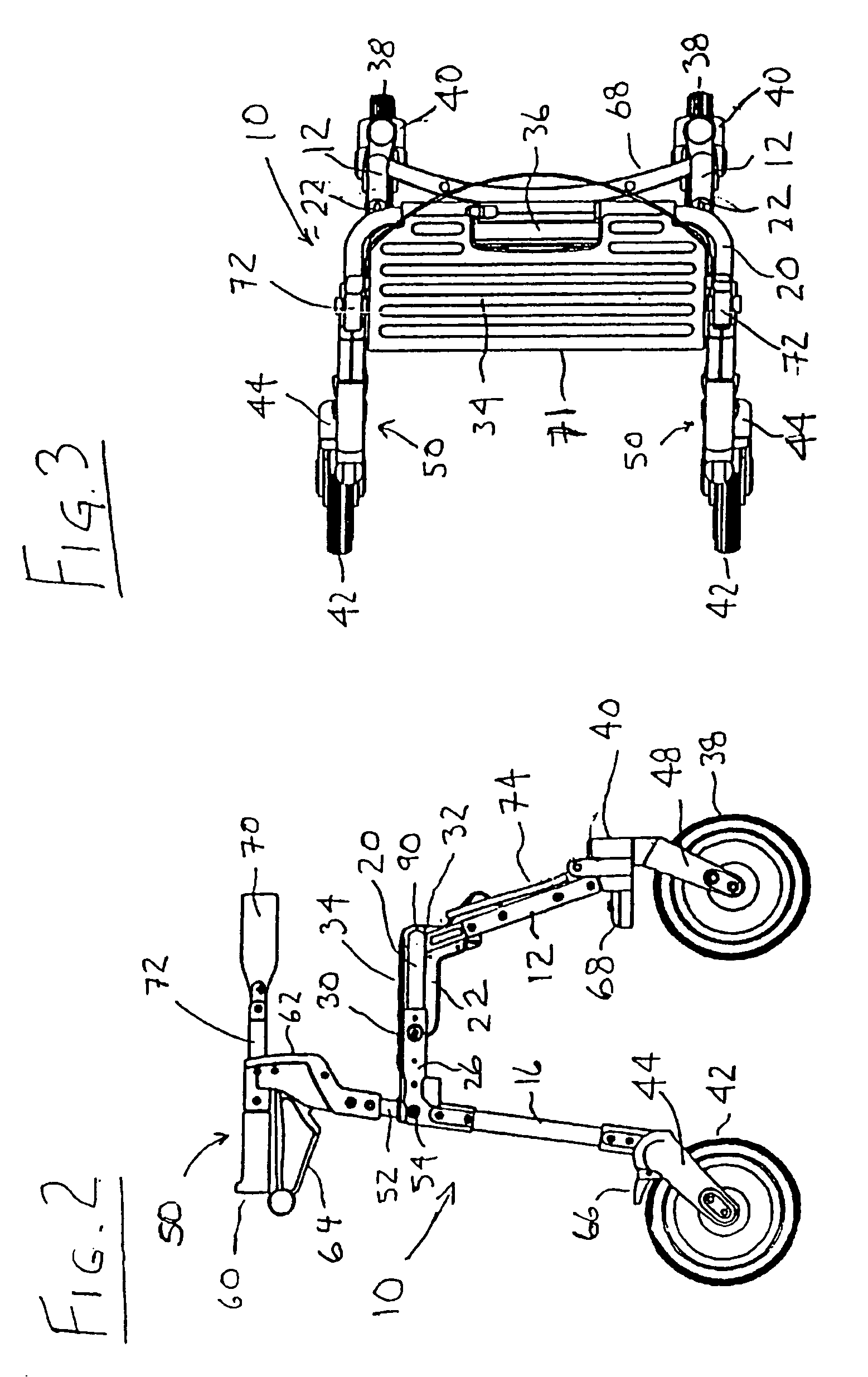
[0068]Referring to FIGS. 1 to 3, there is shown a perspective view of a rollator or walker / transport chair 10 in the walker configuration. Walker / transport chair 10 has a pair of forward leg members 12, a pair or rearward leg members 16, and a U-shaped transverse seat support member 20. Front leg members 12 are fixedly secured at their upper ends to front leg brackets 22, and rear leg members 16 are fixedly attached at their upper ends to rear leg brackets 26. Front leg brackets 22 are pivotally attached to rear leg brackets 26 at pivot pins 30. In the open or operative position shown in FIGS. 1 to 3, abutment surfaces 32 at the upper ends of front leg brackets 22 engage the forward lower edge of seat support member 20, when forward leg members 12 are in the open and weight bearing position. Front leg brackets 22 permit the front leg members 12 to be folded toward rear leg members 16 in order to collapse walker / transport chair 10 into a more compact configuration, e.g. for placement...


PUM


Abstract

The present invention relates to a cordless braking system for a mobility-aiding device, such as a wheeled walker (a rollator) or a transport chair. The cordless braking system includes a brake actuating linkage, disposed inside the leg and handlebar members of the mobility-aiding device, which extends during height adjustment of the handlebars. The brake-actuating linkage and the leg / handlebar of the mobility-aiding device are designed to enable a locking pin or bolt to extend all the way therethrough to ensure that all of the height-adjustable members are secured together during use.

Description

CROSS REFERENCE TO RELATED PRIOR ART[0001]The present application is a continuation-in-part of U.S. patent application Ser. No. 10 / 692,092 filed Oct. 23, 2003, which is a divisional of U.S. patent application Ser. No. 09 / 908,102 filed Jul. 18, 2001, which issued as U.S. Pat. No. 6,659,478 on Dec. 9, 2003, which claims priority from Canadian Patent Application No. 2318028 filed Sep. 12, 2000, all of the United States Patent applications are incorporated herein by reference.BACKGROUND OF THE INVENTION[0002]The present invention relates to a wheeled walker, which can be used as a transport chair, and in particular to a novel braking system for wheeled apparatus.[0003]Many persons, by reason of age or disability have difficulty in walking without a walking aid. Wheeled walkers or rollators are widely used by many such persons to assist in mobility. A wheeled walker typically has a frame mounted on four wheels and a pair of rearwardly extending handlebars, which the user can grip for sup...

Claims


Application Information

Patent Timeline
IPC IPC(8): B62M1/00A61G5/08A61G5/10A61G5/12A61H3/00A61H3/04B60T1/04F16D65/14
CPCA61G5/08A61H3/04B60T1/04A61G2005/0833A61G2005/0883A61G2005/0891A61G2005/1091A61G2005/125A61H2003/046A61H2201/1633F16D2121/14A61G5/0833A61G5/0883A61G5/0891A61G5/1091A61G5/125
Inventor HALLGRIMSSON, BJARKIRICHTER, JEFF
Owner RANDOM PRODS TRUST
Learn More