Lock release operator layout structure in vehicle

a technology of operator layout and lock release, which is applied in the direction of roofs, anti-theft cycle devices, cycle equipment, etc., can solve the problems of complex operation, lock release, and lock unlocking

Inactive Publication Date: 2007-05-22
HONDA MOTOR CO LTD
View PDF8 Cites 16 Cited by
  • Summary
  • Abstract
  • Description
  • Claims
  • Application Information

AI Technical Summary

Benefits of technology

[0016]According to the present invention, since the plurality of lock release operators for respectively releasing the lock conditions of the plurality of containing portions inclusive of the front containing portion are concentratedly disposed on a lateral side of the front containing portion, the operation for releasing the lock conditions of the plurality of containing portions is facilitated.
[0017]According to the present invention, the unlocking, lock releasing, operation by the rider on the rider's seat is further facilitated.
[0023]In order attain the above object, the present invention resides in a containing structure for a vehicle, including an inner cover for covering from the rear side a head pipe of a vehicle body frame at its front end and which constitutes a part of a vehicle body cover. A containing case is mounted to the inner cover in an openable and closable condition. A holding mechanism for temporarily holding the containing case at an intermediate position between a fully closed position and a fully opened position of the containing case when the containing case is opened from the fully closed position is provided between the containing case and the inner cover so that its hold condition can be released.
[0029]According to the present invention, the hold release operating member can be arranged at such a position wherein it can be easily operated at the time of releasing the condition where the containing case is temporarily held by the holding mechanism.
[0030]Furthermore, according to the present invention, when an unlocking force is exerted to put the case lock mechanism into an unlocking operation, the containing case is slid from the fully closed position towards the opening side by the spring biasing force of the spring means, so that a part of the containing case projects from the inner cover. Therefore, it can easily be confirmed visually by the rider that the case lock mechanism has been put into the unlock condition. Moreover, the containing case can be drawn out with a small operating force.

Problems solved by technology

In such cases, since the operating portions for releasing the lock conditions are apart from each other in the conventional motorcycle, the unlocking, lock releasing, operation is intricate to carry out.

Method used


Image

  • Lock release operator layout structure in vehicle
  • Lock release operator layout structure in vehicle
  • Lock release operator layout structure in vehicle

Examples


Embodiment Construction

[0056]Now, a mode for carrying out the present invention will be described below, based on one embodiment of the present invention shown in the accompanying drawings.

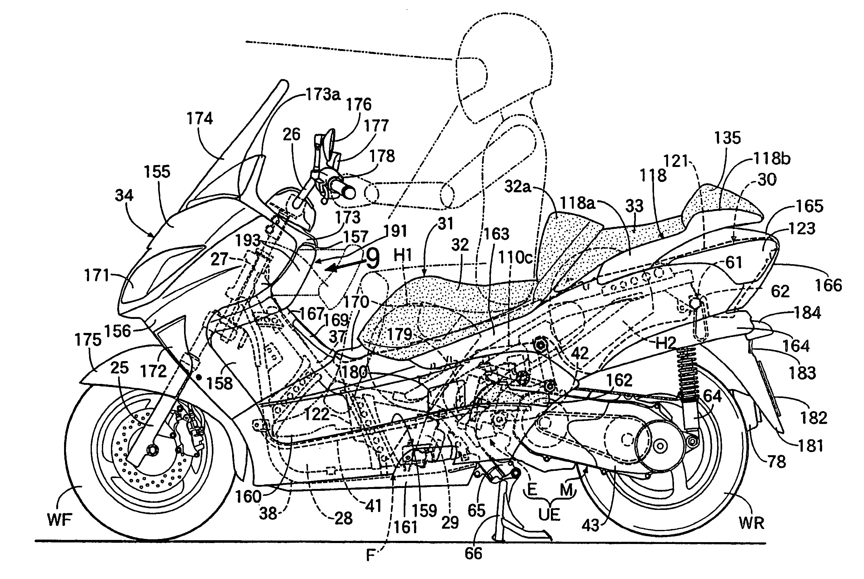
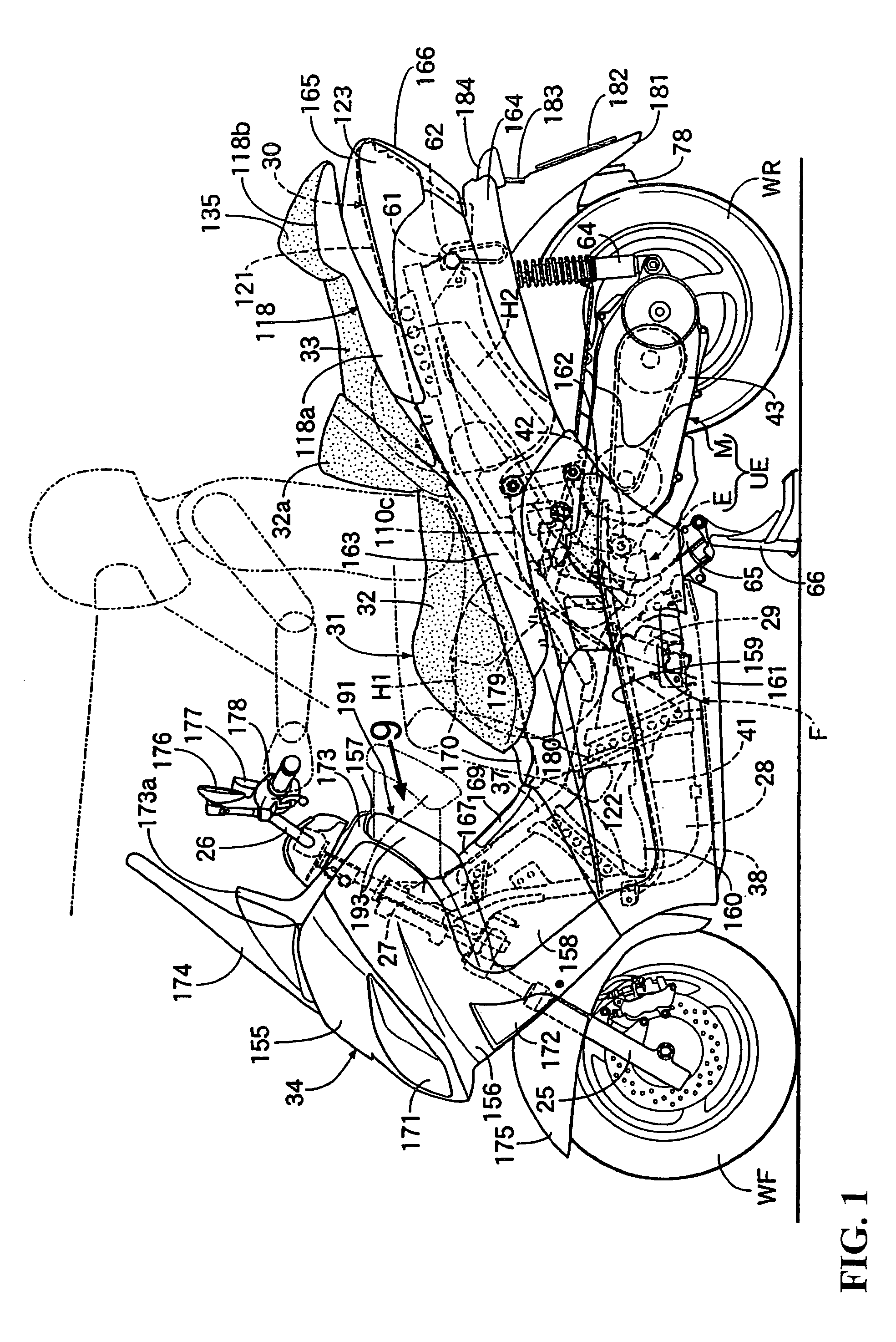
[0057]As illustrated in FIG. 1, a vehicle body frame F of a motor scooter type vehicle includes, at the front end thereof, a front fork 25 for rotatably supporting a front wheel WF, and a head pipe 27 for steerably supporting a steering handle 26 connected to the front fork 25. A unit swing engine UE for supporting a rear wheel WR at the rear end thereof is vertically swingably supported on an intermediate portion in the front-rear direction of the vehicle body frame F. On the front side relative to the unit swing engine UE, a fuel tank 28 is a functional component part formed to be vertically elongated in a side view with a radiator 29 disposed on the rear side relative to the fuel tank 28 and mounted on the vehicle body frame F. In addition, a rider's seat 31, configured in a tandem form having a front seat 32 and a r...


PUM


Abstract

In a vehicle including a plurality of containing portions, namely, a front containing portion provided in an inner cover covering from the rear side a head pipe of a vehicle body frame at its front end and constituting a part of a vehicle body cover which can be locked in a fully closed condition, to facilitate the operation for releasing the lock conditions of the plurality of containing portions. A plurality of lock release operating buttons for respectively releasing the locked conditions of a plurality of containing portions inclusive of a front containing portion is disposed at an inner cover on a lateral side of the front containing portion.

Description

CROSS-REFERENCE TO RELATED APPLICATIONS[0001]The present application is related to Japanese Patent Application Nos. 2004-012504 and 2004-012503 both filed on Jan. 20, 2004 the entire contents of which are hereby incorporated by reference.BACKGROUND OF THE INVENTION[0002]1. Field of the Invention[0003]The present invention relates to a vehicle including a plurality of containing portions which include a front containing portion provided in an inner cover covering from the rear side a head pipe with a vehicle body frame at its front end and including a part of a vehicle body cover which can be locked in a fully closed condition. More particularly to a layout structure for a plurality of lock release operators for respectively releasing the lock conditions of the plurality of containing portions.[0004]The present invention also relates to a containing structure for a vehicle, including an inner cover for covering from the rear side a head pipe of a vehicle body frame at its front end a...

Claims


Application Information

Patent Timeline
Patent Type & Authority Patents(United States)
IPC IPC(8): B60R5/00B62H5/00B62J7/06B62J9/00B62J35/00B62J99/00B62K19/46
CPCB62H5/00B62K19/46B62J35/00B62K2202/00B62J9/00B62J7/06B62J99/00
Inventor KAMEMIZU, FUMINORIYANO, KENGOYAMAGUCHI, NOBUOMORI, KAZUHIKOMATSUI, NORIYUKIHATAYAMA, ATSUSHI
Owner HONDA MOTOR CO LTD
Why Eureka
Try Eureka