Vehicle front body structure

a front body and vehicle technology, applied in the direction of roofs, transportation and packaging, vehicle arrangements, etc., can solve the problems of increasing the rigidity of the joined parts, and achieve the effect of reducing the impact energy acting, simple configuration, and high rigidity

Active Publication Date: 2007-05-22
HONDA MOTOR CO LTD
View PDF17 Cites 46 Cited by
  • Summary
  • Abstract
  • Description
  • Claims
  • Application Information

AI Technical Summary

Benefits of technology

[0011]Thus, in this invention, since the first end portions of the right and left connecting members are transversely extended through the front side members in front of the right and left wheel houses, respectively, each of which being welded to the both sides of the front side member it extends through, the rigidity of joints at which the first end portions of the connecting members are joined to the front side members (that is, base portions of the connecting members) is sufficiently increased by the simple configuration.
[0012]As a result, when impact energy acts on either front upper member from the front of the body, the impact energy is transmitted from the front upper member to the front side member via the connecting member and the joint (the base portion of the connecting member) of high rigidity. The front side member and the front upper member then plastically deform, thereby sufficiently mitigating the impact energy acting toward the passenger compartment. That is, the impact energy acting on the front upper member is absorbed not only by the front upper member but also by the front side member sufficiently.
[0013]As described above, in this invention, the simple configuration allows impact energy at an offset impact on the front of the body to be dispersed into the front side member and the front upper member, so that the impact energy is efficiently absorbed by the front body part. As a result, the impact energy acting toward the passenger compartment is further mitigated.
[0014]Since front portions of the front side members and front portions of the front upper members are connected by the connecting members, the rigidity of the front body part is increased, and the rigidity of the body as a whole including a passenger compartment part is increased.
[0015]Further, since the first end portion of each connecting member is attached to the front side member in a transversely penetrating manner, the mounting position of the connecting member relative to the front side member is more easily improved in accuracy.
[0016]Preferably, the right and left front side members each comprises a hollow member having an inner side member half toward a vehicle width center line and an outer side member half laterally outside, the inner and outer side member halves having a through-hole formed to allow the first end portion of the connecting member to extend therethrough, and the first end portions of the right and left connecting members are each joined to a joining flange placed against and joined to the outer side member half from laterally outside. Thus, the welding operation for the joints between the connecting members and the front side members can be performed in stages at different times to prevent welding heat distortion.

Problems solved by technology

However, with this structure as it is, there is a limit to increase the rigidity of the joined portions.

Method used


Image

  • Vehicle front body structure
  • Vehicle front body structure
  • Vehicle front body structure

Examples


Embodiment Construction

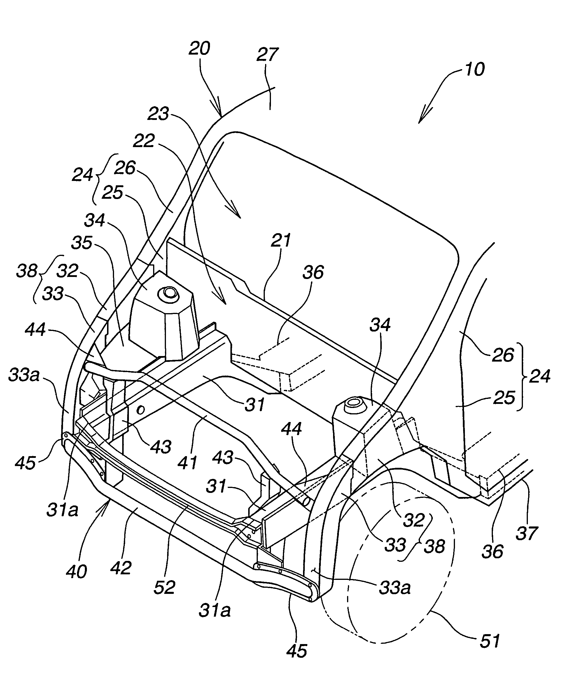
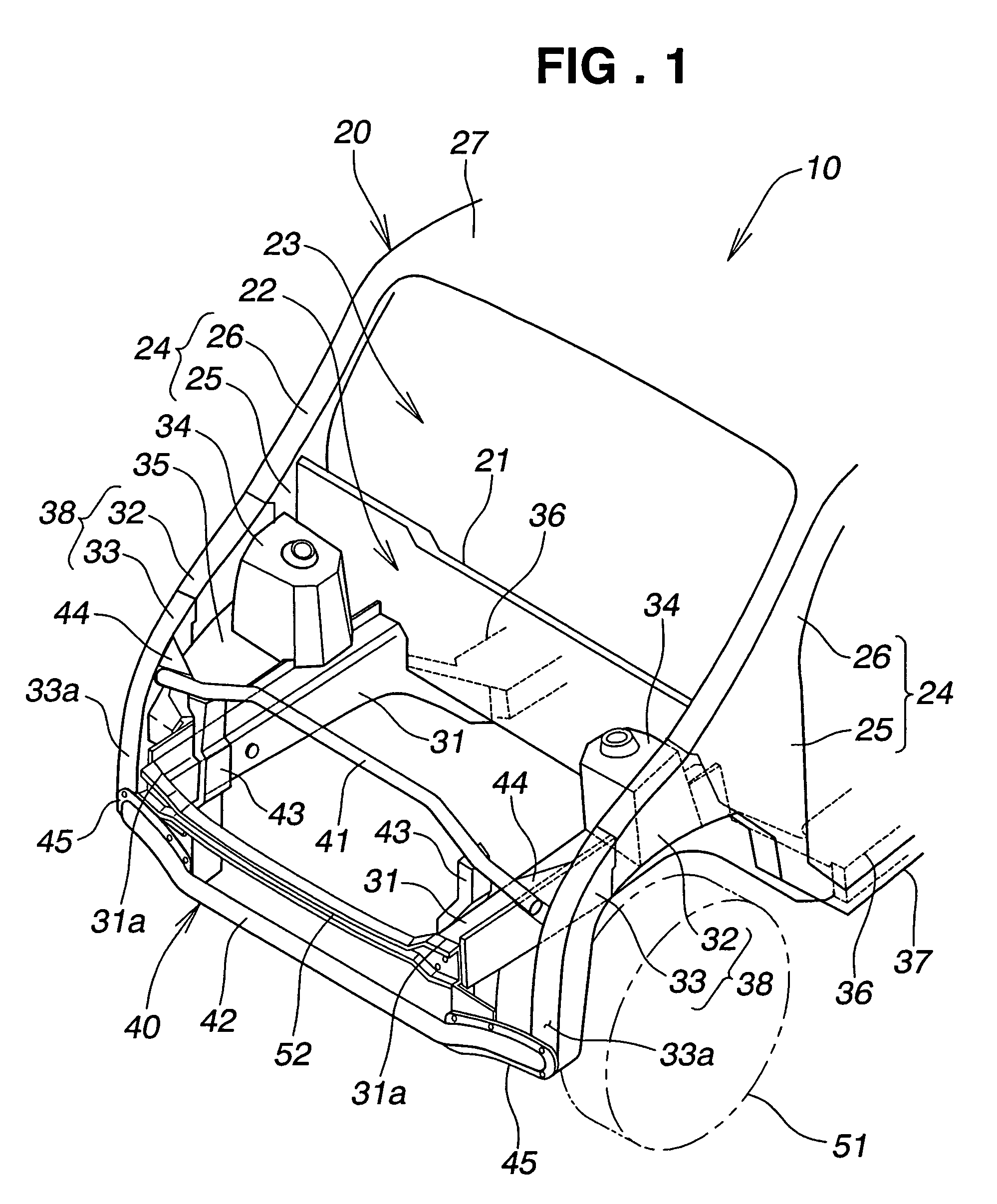
[0031]A vehicle 10 shown in FIG. 1 has a body 20 (i.e., a body frame 20) partitioned into a front engine compartment 22 and a rear passenger compartment 23 by a dashboard 21, and has right and left front pillars 24, 24 put upright near the dashboard 21.

[0032]A front structure of the body 20 having a monocoque structure will be described below. A “front part of the body 20” herein means a portion forward of the dashboard 21 and the front pillars 24, 24 in the body 20. The dashboard 21 is a partition board and is also called a dash panel. The front pillars 24, 24 are column supports disposed between a windshield and side glasses.

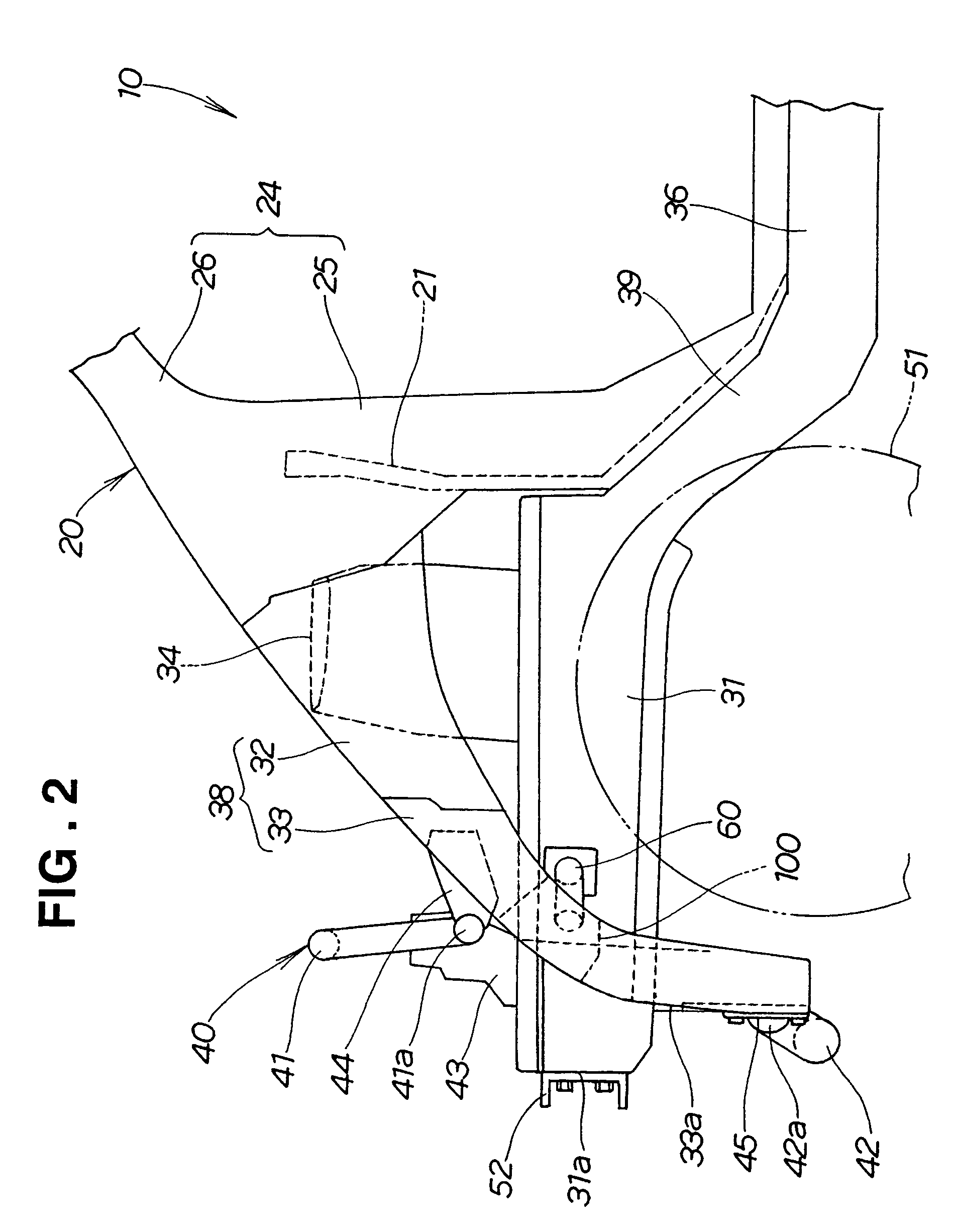
[0033]The front part of the body 20 has the structure in which a pair of right and left front side members 31, 31 are extended longitudinally on the right and left sides of the front body part; right and left upper members 32, 32 are extended forward from the right and left front pillars 24, 24, laterally outside of and above the front side members 31, 31; rig...


PUM


Abstract

Front upper members and front side members located laterally inward of the front upper members are joined with connecting members of pipe form. A first end portion of each connecting member extends through the front side member and is welded to both sides of the side member. The joint has high rigidity. When impact energy acts on either front upper member, the energy is transmitted to the front side member via the connecting member, and the front side member and the front upper member plastically deform.

Description

FIELD OF THE INVENTION[0001]The present invention relates to an improvement in a vehicle front body structure. A “front body part” herein means a portion forward of front pillars and a dashboard.BACKGROUND OF THE INVENTION[0002]A vehicle front body structure designed to allow a front body part to absorb collision energy in a vehicle frontal crash is disclosed, for example, in Japanese Patent No. 2516212. The vehicle front body structure will be described with reference to FIGS. 12 and 13.[0003]A conventional vehicle body 200 has a pair of right and left front side members 201, 201 extending longitudinally of the body on the right and left sides of its front part. Right and left front upper members 202, 202 (only the right one shown) extend longitudinally of the body, laterally outside of and above the front side members 201, 201. Right and left wheel houses 203, 203 are provided between the right and left front side members 201, 201 and the right and left front upper members 202, 20...

Claims


Application Information

Patent Timeline
Patent Type & Authority Patents(United States)
IPC IPC(8): B62D25/08B62D21/15B62D25/20
CPCB62D21/152B62D25/082
Inventor GOMI, TETSUYAOTSUKA, YASUHIKO
Owner HONDA MOTOR CO LTD
Why Eureka
Try Eureka