Imaging apparatus with a multifocal lens formed of two pieces with different focal lengths

a multi-focal lens and imaging apparatus technology, applied in the field of imaging apparatus, can solve the problems of difficult to read a complicated image, unpractical, high operation and handling difficulty of the above mentioned specialized scanner, etc., and achieve the effects of improving decoding accuracy, high quality image, and convenient, quick and precise optimization of distan

Inactive Publication Date: 2007-05-22
RIVERBELL
View PDF30 Cites 29 Cited by
  • Summary
  • Abstract
  • Description
  • Claims
  • Application Information

AI Technical Summary

Benefits of technology

[0064]When the illuminating means for illuminating a second object by illumination from the screen of the displaying means is provided, the reading of the second object is performed while it is illuminated by the illuminating means in order to obtain a clear image of the second object, thereby improving the decoding precision.
[0065]Furthermore, in the above-mentioned imaging apparatus, it is desirable to include an antenna for wireless transmitting and re

Problems solved by technology

However, using the above mentioned specialized scanner is highly complicated in operation and handling, and thus it is not practical.
In addition, when the lens for imaging an object at a normal distance is used to read a bar code as described above, it is difficult to read a complicated im

Method used


Image

  • Imaging apparatus with a multifocal lens formed of two pieces with different focal lengths
  • Imaging apparatus with a multifocal lens formed of two pieces with different focal lengths
  • Imaging apparatus with a multifocal lens formed of two pieces with different focal lengths

Examples


first embodiment

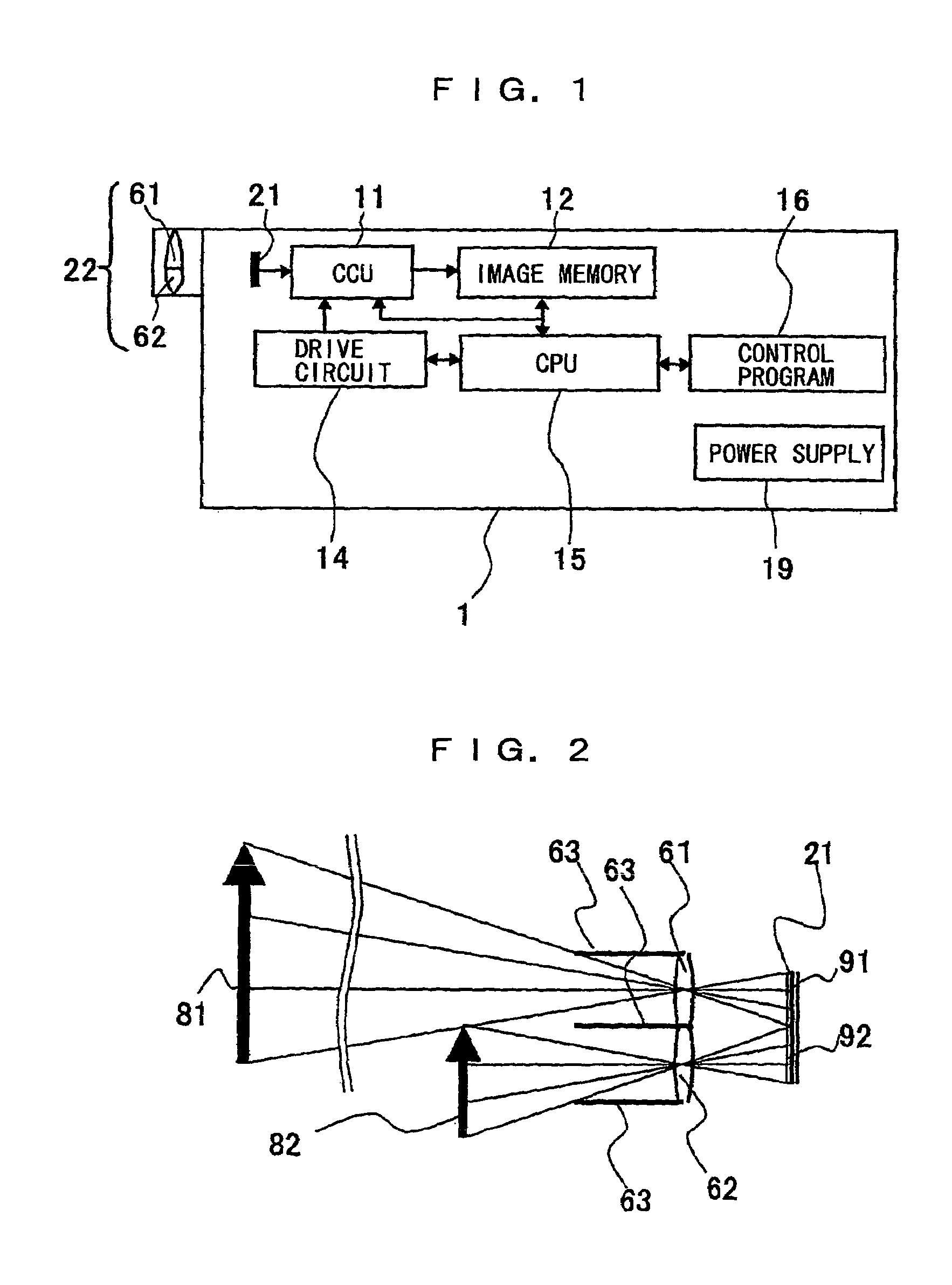
[0085]FIG. 1 is an overall structure view showing the imaging apparatus 1 of the first embodiment of the present invention. FIG. 2 is an explanatory view showing an effect of the imaging lens 22 of the imaging apparatus 1.

[0086]In FIG. 1, the imaging apparatus 1 includes an imaging lens 22 for imaging the first and the second objects 81 and 82 (refer to FIG. 2), an imaging device 21 for capturing an image formed by the imaging lens 22, a camera control unit (hereinafter, abbreviated to “CCU”) 11 for controlling image qualities of image signals of the first and the second objects 81 and 82 abstracted from the imaging device 21, and an image memory 12 for storing the image signals processed by the CCU 11 as moving images or still images.

[0087]The imaging apparatus 1 also includes a drive circuit 14 for driving the imaging device 21, a central processing unit (hereinafter, abbreviated to “CPU”) 15 for performing an operation process on the image signals of the second object 82 stored i...

second embodiment

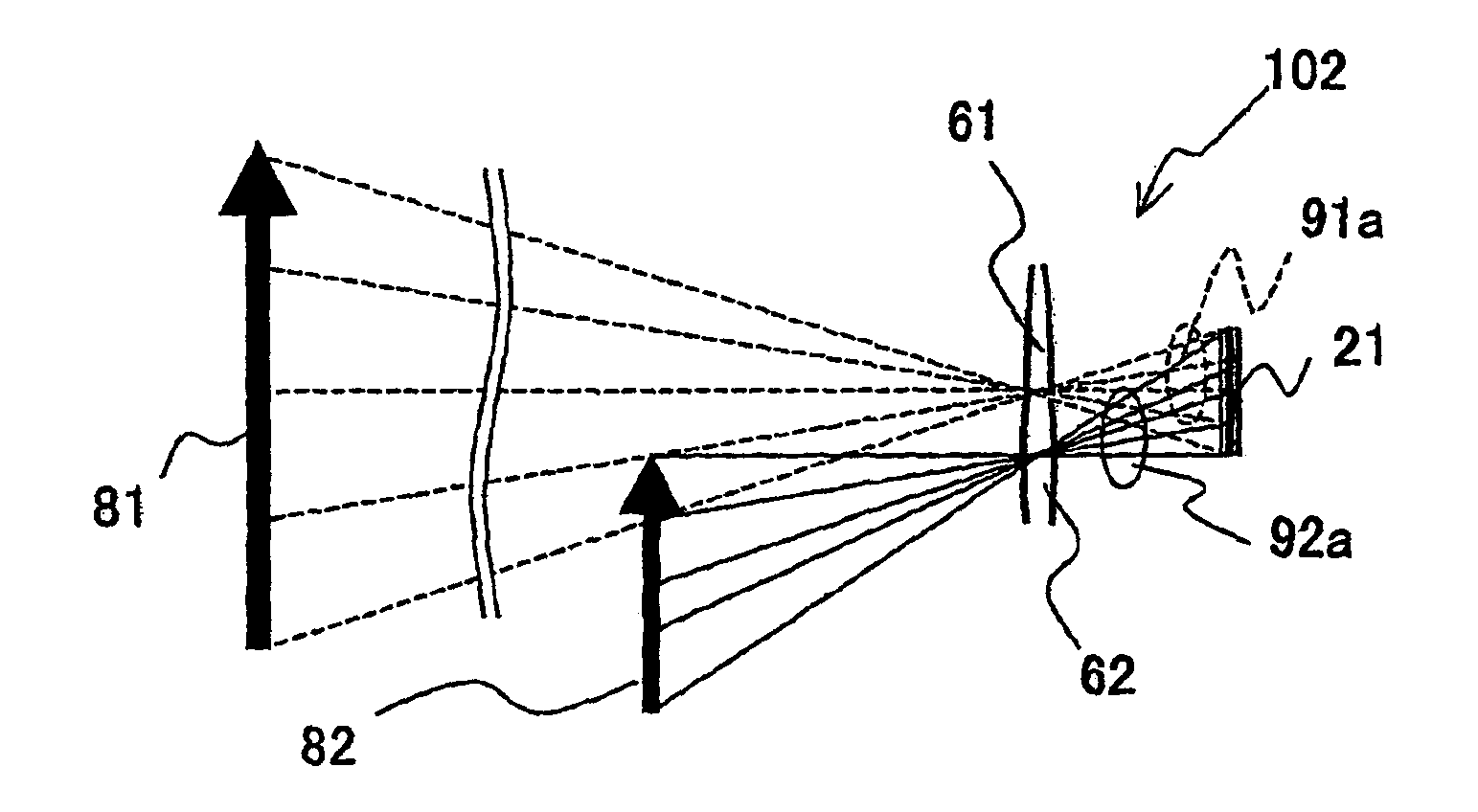
[0102]FIG. 3 is an explanatory view showing an effect of the imaging lens provided in the imaging apparatus 102 of the second embodiment of the present invention.

[0103]In FIG. 3, the imaging apparatus 102 has a structure excluding the shields 63 (refer to FIG. 2) which are respectively placed in the vicinities of the first and the second lens portions 61 and 62 in the imaging apparatus 1 of the aforementioned first embodiment. Since the rest of the structure is the same as that of the imaging apparatus 1 of the aforementioned first embodiment, the same reference numerals are designated to the same components to omit explanations in detail, and only the different components will be explained below.

[0104]As shown in FIG. 3, when the shields 63 are removed, light 91a (dashed line in the view) that passes through the first lens portion 61 is incident on the whole plane of the imaging device 21. Similarly, light 92a (solid line in the view) that passes through the second lens portion 62 ...

third embodiment

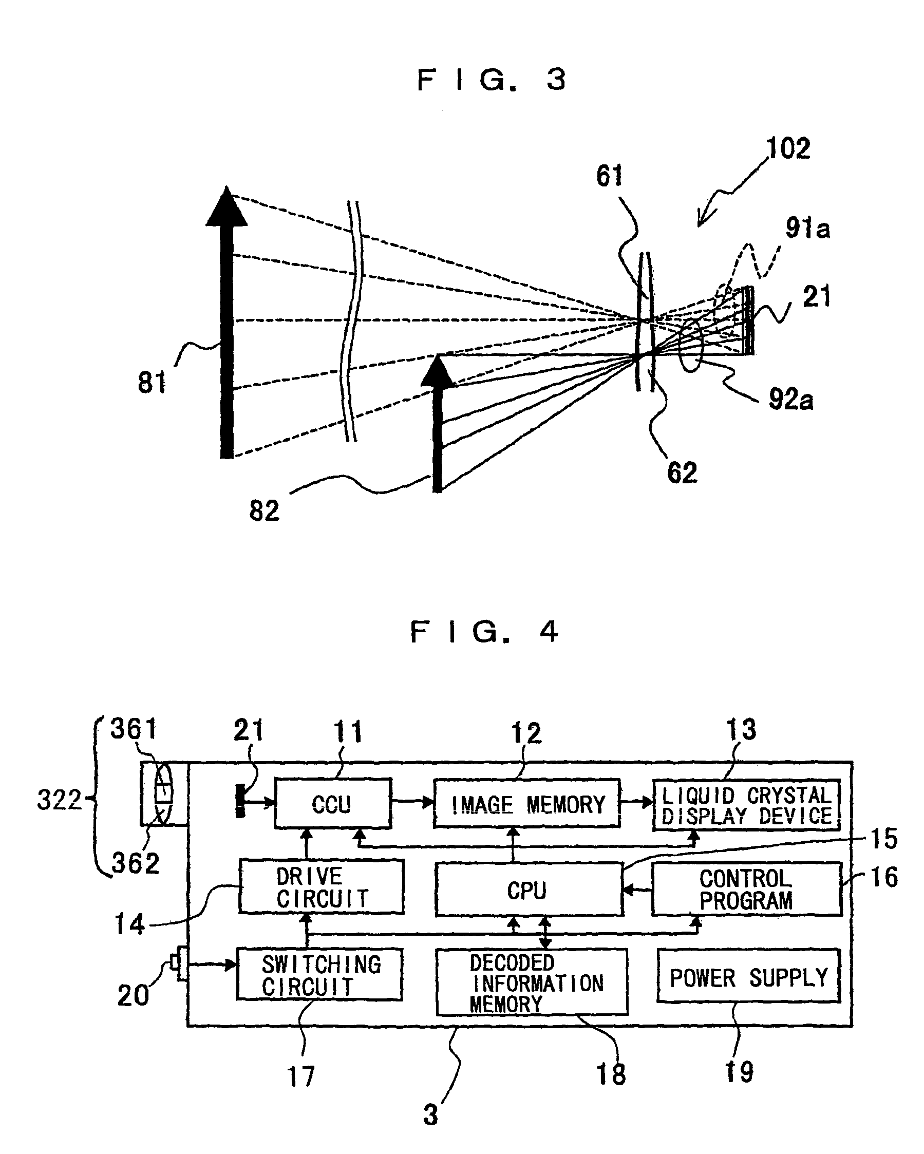
[0106]FIG. 4 is an overall structure view showing the imaging apparatus 3 of the third embodiment of the present invention, and FIG. 5 is an enlarged view showing the imaging lens 322 of the imaging apparatus 3. The FIG. 6 and FIG. 7 are explanatory views showing effects of the imaging lens 322 of the imaging apparatus 3.

[0107]In FIG. 4, the imaging apparatus 3 has the structure of the imaging apparatus 1 (refer to FIG. 1) of the aforementioned first embodiment, to which are added a liquid crystal display device 13 as a displaying means for displaying various information on a screen, a not-shown optical shutter arranged between the imaging lens 322 and the imaging device 21, a switching circuit 17 for switching and selecting a first lens portion 361 and a second lens portion 362 by the optical shutter, a switch 20 for operating the switching circuit 17, and a decoded information memory 18 for storing information obtained by decoding an image data of the second object 82 (refer to FI...


PUM


Abstract

An imaging apparatus for imaging a first object at a normal distance and a second object nearer than the first object readily with high precision. The imaging apparatus has an imaging lens, an imaging device for capturing an image formed by the imaging lens, and a camera control unit. The imaging lens is a multifocal lens and contains a first lens portion having a first focal length for imaging the first object (e.g., the user of the imaging apparatus) at a normal distance and a second lens portion having a second focal length for imaging the second object (e.g., a bar code) nearer than the first object. The first and second lens portions are arranged on the same plane and formed in one piece. The information collected by imaging the second object is used for processing such as communications or displays.

Description

BACKGROUND OF THE INVENTION[0001]The present invention relates to an imaging apparatus having an image input function such as a personal digital assistant (PDA), a mobile telephone (including the Personal Handy-phone System (PHS)), a remote controller for consumer electronics such as a television or a videocassette recorder, a personal computer equipped with a camera, a monitoring camera, and so forth. For example, the imaging apparatus can be used for imaging a still image or a moving image of an object at a normal distance such as the user of the imaging apparatus or for reading a close up still image such as a digital code, characters, or the like with high precision. Then, the read image is displayed as it is, or the read image data is decoded to collect the information included in the digital code or the characters therein, so that the collected information can be displayed or used for various processes such as communication or the like.[0002]Generally, an imaging apparatus hav...

Claims


Application Information

Patent Timeline
IPC IPC(8): H04N5/225H04B7/00H04B3/10H04M1/00G06F15/02G02B3/10G03B15/05G03B17/18G06K7/10G06T1/00H04N1/107
CPCG02B3/10G02B27/0075H04N1/107H04N23/58
Inventor FUJITA, TSUTOMUKANEGAE, MASATOMO
Owner RIVERBELL
Why Eureka
Try Eureka