Eureka AIR delivers breakthrough ideas for toughest innovation challenges, trusted by R&D personnel around the world.

Wavelength locker with liquid crystal tunable filter generating transmitted and reflected outputs

a wavelength locker and liquid crystal tunable filter technology, applied in the field of wavelength lockers, can solve the problems of laser detune from the desired lock frequency, unintentional detune of the laser from the desired lock point, and high interference with the performance of communications, and achieve the effect of long life and small physical siz

Active Publication Date: 2007-05-22
OCLARO TECH INC
View PDF69 Cites 25 Cited by
  • Summary
  • Abstract
  • Description
  • Claims
  • Application Information

AI Technical Summary

Benefits of technology

[0014]It is a feature of the present invention to develop a wavelength locker that may be configured to operate robustly over a long period of time.

Problems solved by technology

In a DWDM system, mistuning is highly detrimental to the performance of communications since DWDM components exhibit wavelength-dependent losses.
However, one known issue with the use of Fabry Perot etalon as a reference element in a wavelength locker is that power fluctuations in the input light are also capable of producing changes in the etalon transmission signal that mimic a frequency change, resulting in the potential to unintentionally detune the laser from the desired lock point.
Another known issue with the use of Fabry Perot etalon as a reference element in a wavelength locker is that temperature fluctuations to the etalon changes the optical path length of the etalon due to the material's thermal coefficient of expansion, thereby changing the FSR and peak locations of the Fabry Perot etalon and causing the laser to detune from the desired lock frequency.
Epoxies and adhesives used to assemble wavelocker systems are notorious for age-dependent power losses, outgassing, and inadvertent etalon effects.

Method used


Image

  • Wavelength locker with liquid crystal tunable filter generating transmitted and reflected outputs
  • Wavelength locker with liquid crystal tunable filter generating transmitted and reflected outputs
  • Wavelength locker with liquid crystal tunable filter generating transmitted and reflected outputs

Examples


Embodiment Construction

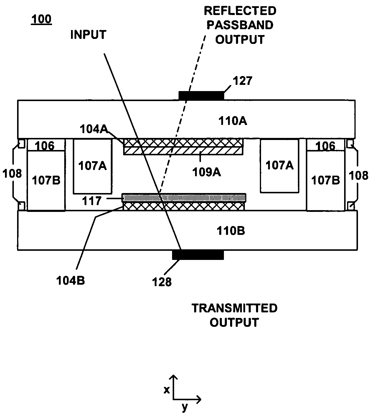
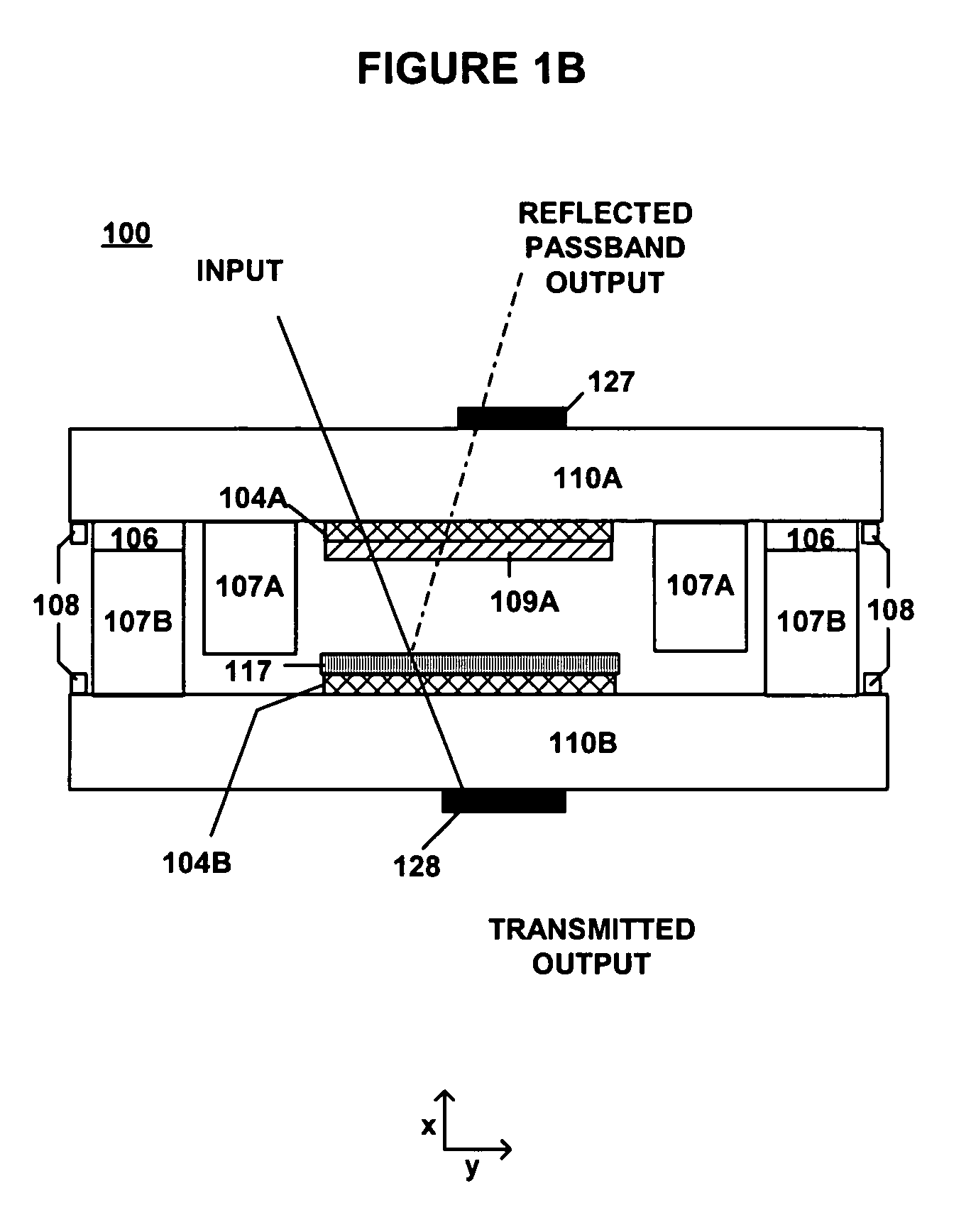
[0033]Throughout this application, like reference numbers as used to refer to like elements. For instance, the two substrates used to form the tunable filter of the present invention are referred to throughout this applications as 110A and 110B. Those supporting elements and features of the invention that are distributed on each substrate and later combined may be referred to under their index reference for a particular substrate XA, XB or for simplicity sake, under the shared reference X. In certain cases, a designated signal output from any device X may be referred to as X′.

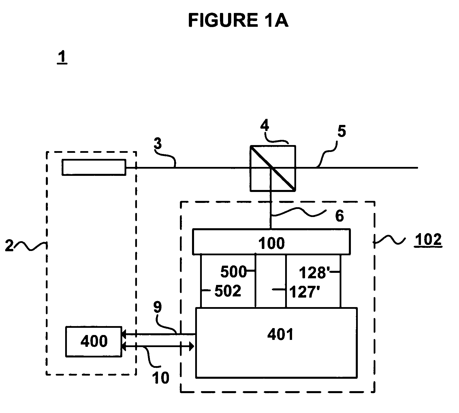
[0034]A preferred embodiment of the present invention is presented in FIG. 1A, which shows a laser system 1 having a laser transmitter 2, tap 4 and liquid crystal wavelocker 102 including a tunable filter 100.

[0035]The description herein shall treat the laser transmitter and wavelocker devices as having independent control electronics. As so, for clarity sake and to facilitate a description that delineates the ...


PUM

PropertyMeasurementUnit
alpha angleaaaaaaaaaa
depthaaaaaaaaaa
depthaaaaaaaaaa

Abstract

A wavelength locker operates with a reference tunable liquid crystal filter having integrated photodetectors deposited on the front and backside of the liquid crystal cell to track power intensity of the accepted passband signal and its rejected signal compliment at a 50% power point where the two signals cross on the side of the filter transmission peak. The tunable filter is tuned by an offset wavelength from the laser wavelength such that 50% power is transmitted through the filter at the center wavelength of the laser. The wavelength locker may be configured with a liquid crystal tunable etalon or a liquid crystal tunable bandpass filter. A method for locking an optical signal to a desired frequency is also included and provides a substantially linear feedback signal computed by dividing the rejected signal power by the accepted signal power and passing it to laser transmitter to enable it to correct for frequency drift. Optional features of the present invention include an integrated thermal sensor and heater and temperature compensation control schemes.

Description

CROSS-REFERENCE TO RELATED APPLICATIONS[0001]This application is a continuation of and claims priority from commonly assigned application Ser. No. 10 / 453,455 titled “Narrow Band Tunable Filter with Integrated Detector”, filed Jun. 2, 2003 now U.S. Pat. No. 7,009,680.FIELD OF INVENTION[0002]This invention generally relates to wavelength lockers, and more particularly, to a wavelength locker suitable for use with fixed and tunable lasers.BACKGROUND OF THE INVENTION[0003]Laser frequency locking is an essential technology for optical communications and other fields. In telecommunications, Dense Wavelength Division Multiplexing (DWDM) systems require tight control and accurate tuning of each frequency propagated down an optical fiber by a communication laser. In DWDM, each of a plurality of laser signal sources is tuned in frequency to a distinct channel, allowing a plurality of signals to be simultaneously transmitted down a single optical fiber. In this way, large volumes of informatio...

Claims


Application Information

Patent Timeline
Patent Type & Authority Patents(United States)
IPC IPC(8): G02F1/13G02F1/21
CPCG02F1/216G02F2201/307G02F2201/58G02F2203/055G02F2203/06
Inventor CAVANAUGH, SHANTI A.HOOD, JAMES M.MOLINARI, LOUIS J.
Owner OCLARO TECH INC
Why Eureka
Eureka Blog
Learn More