Method for generating a focused image of an object

a focused image and object technology, applied in the field of machine vision, can solve the problems of inherently difficult inspection of the end face of a fiber optic cable, degradation of performance, and many inspection operations of human operators performing manual inspection, and achieve the effect of excluding the composite image, low sharpness measurement, and reducing the difficulty of manual inspection

Inactive Publication Date: 2007-05-22
COGNEX TECH & INVESTMENT
View PDF33 Cites 81 Cited by
  • Summary
  • Abstract
  • Description
  • Claims
  • Application Information

AI Technical Summary

Benefits of technology

[0009]This invention overcomes the disadvantages of the prior art by providing a focused image by generating a composite image of images that may be acquired at several focus settings. In one general aspect of the invention, an image with at least one region is acquired. A fine feature sharpness measurement performed on the region to produce a sharpness score for the region. The sharpness score is used to determine a spatial weighting. A composite image can then be computed by using the acquired image and the spatial weighting. For example, if an image region exhibits a high degree of fine feature sharpness characteristics, it will be weighted highly in the weighting image, and therefore, factored heavily in the composite image. A blurry image region, with a resulting low sharpness measurement is effectively excluded from the composite image.

Problems solved by technology

Many inspection operations can be extremely tedious for human operators performing manual inspection, and the application of machine vision is typically used to improve the consistency and accuracy of an inspection operation, while relieving an inspection operator from performing the task.
Scratches, cracks, and debris on critical areas of the interconnection interface may result in defective operation, or result in a degradation of performance.
Inspection of the end face of a fiber optic cable is inherently difficult because of the properties and characteristics of the fiber.
The translucent nature of the fiber optic cable contributes to difficult lighting conditions since illumination intended for inspection of the surface also enters the fiber, and may reflect back into the machine vision system, causing image noise.
However, since the fiber end surface is typically non-planar, it is difficult to acquire a single image of the fiber end surface for inspection that is optimally focused, because the depth of field at high magnification is typically less than the extent to which the surface is non-planar.
While this method is effective for evaluation of surface features having a non-zero depth, its utility is limited to planar surfaces.
Other known methods suggest the acquisition of multiple sectional images from a single focus setting, and combining the sectional images into a single combined image, though such an apparatus can be extremely complex.

Method used


Image

  • Method for generating a focused image of an object
  • Method for generating a focused image of an object
  • Method for generating a focused image of an object

Examples


Embodiment Construction

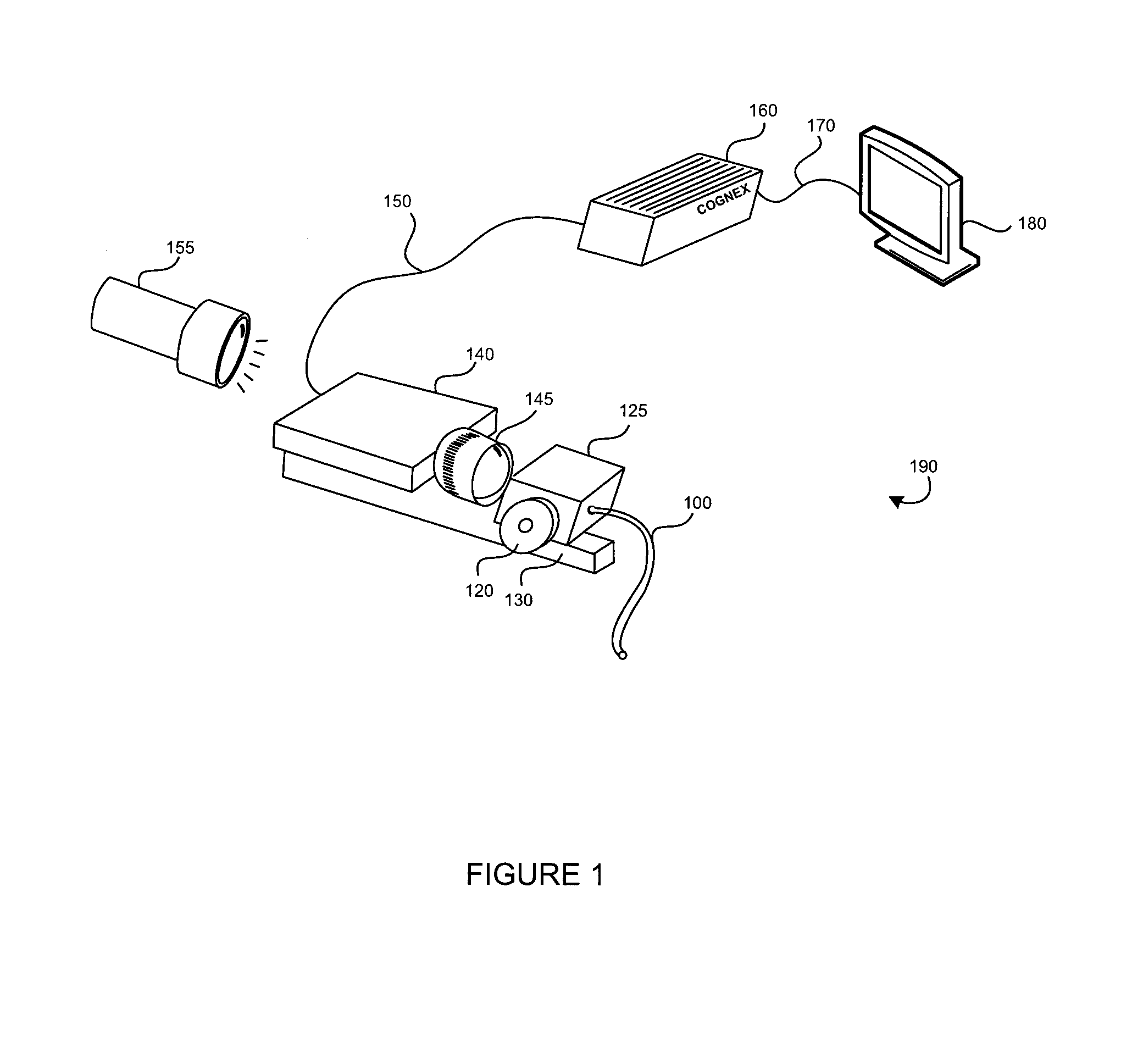
[0028]FIG. 1 depicts a fiber optic fiber end inspection system 190 used to inspect the end face of a fiber optic cable 100. A camera 140 having a lens 145 is mounted to an inspection frame 130 and directed to an inspection fixture 125. The fiber optic cable 100 end face is presented to the lens 145 by inserting the fiber optic cable 100 end into the inspection fixture 125. A typical fiber optic end inspection system 190 will employ a microscope adapted for inspection of fiber, or fiberscope, to provide significant magnification of the fiber optic cable 100 end as it is presented to the lens 145 of the camera 140. The fiber optic cable 100 end face is illuminated by a light source 155. The inspection fixture 125 has a focus adjustment mechanism 120 that facilitates translation of the inspection fixture 125 relative to the camera 140 and inspection frame 130. Rotation of the focus adjustment mechanism 120 changes the distance between the lens 145 and the inspection fixture 125. One sk...


PUM


Abstract

A method is provided for computing a composite image representing a focused image of an object in an application of machine vision in an optical inspection system. An image tessellated into focus regions is evaluated by region for fine feature sharpness. A sharpness image is computed for each focused region using a fine feature sharpness measurement. A focused composite image is computed by combining as a weighted average, the images at several focus settings, using the sharpness image at each focus setting as the weight. The focused composite image can be further analyzed, inspected, or otherwise processed.

Description

CROSS-REFERENCE TO RELATED APPLICATIONS[0001]The present invention is related to the commonly assigned U.S. Pat. No. 6,632,298 entitled “Method and Apparatus for Focusing an Optical Inspection System,” the content of which is expressly incorporated herein by reference.BACKGROUND OF THE INVENTION[0002]This invention relates to the field of machine vision, and its application in obtaining an optimally focused image of an object under analysis. Specifically, the invention addresses a need for obtaining an optimally focused image under high magnification of a portion of a transparent or translucent surface that is not perfectly flat, though, it can be used to inspect the surface of virtually any object.[0003]Inspection operations in an industrial environment are typically performed to characterize manufacturing operations, and to ensure that quality and product specification requirements are met. Many inspection operations can be extremely tedious for human operators performing manual i...

Claims


Application Information

Patent Timeline
Patent Type & Authority Patents(United States)
IPC IPC(8): G06K9/40G03B13/00G06K9/00G06K9/56G06K9/68H04N5/232G03B17/00G06K9/32H04N5/228
CPCG03B13/36H04N5/23212G02B6/3843G02B6/385G01M11/088G01M11/31H04N23/673H04N23/675
Inventor BACHELDER, IVAN
Owner COGNEX TECH & INVESTMENT
Why Eureka
Try Eureka