Trim clip installation tool and method

Inactive Publication Date: 2007-05-29
HONDA MOTOR CO LTD
View PDF25 Cites 4 Cited by
  • Summary
  • Abstract
  • Description
  • Claims
  • Application Information

AI Technical Summary

Benefits of technology

[0010]The tool and process of the present invention satisfies the aforementioned need. More specifically, the tool and process of the present invention allows a trim clip, particularly an adhesive-backed trim clip, to be removed from a storage medium and applied directly to a vehicle surface with a predetermined amount of setting force. The design of the tool facilitates setting of the trim clip with minimal impact to the user's hand(s), thereby minimizing or eliminating hand stress concerns. Further, because only the tool need touch the trim clip, contamination of the adhesive backing is also minimized.
[0011]The tool includes a handle attached to a grasping portion. The grasping portion is designed to easily engage a trim clip while it resides on a storage medium, such as a mounting film used with adhesive-backed trim clips. Once engaged, the tool can be used to remove the trim clip and securely transport it to the vehicle to which it will be installed. When applicable based on the particular type of trim clip being used, the tool is also preferably provided with a mechanism by which a user can easily determine that the clip has been set to the vehicle with adequate force. Once the trim clip has been properly installed to the vehicle, the clip may be easily released by the tool.

Problems solved by technology

With respect to the installed location and orientation of a trim clip, it can be easily understood that if a trim clip is installed in the wrong location and / or in an incorrect orientation, the trim piece that the clip is designed to retain may not mate properly thereto.
Depending on the design, size, shape and / or other characteristics of the trim clip of interest and the location on the vehicle to which the trim clip is to be installed, meeting one or all of these criteria may be problematic.
First, adhesive-backed trim clips require that a sufficient amount pressure be exerted thereupon during installation to the vehicle.
Absent the exertion of such pressure, it is quite possible that the trim clip will not be sufficiently adhered to the vehicle, and may become dislodged.
In addition, there is often little or no indication on the vehicle as to the proper location and / or orientation of the trim clip.
Meeting these criteria may be difficult for several reasons.
However, the design, size, shape and / or other characteristics of a given trim clip can make grasping and or installing the trim clip by hand very difficult—particularly if a worker must wear gloves.
This situation can be compounded by the need to place a trim clip in a hard to reach location on / in the vehicle.
Repeated application of trim clips with adequate setting force can also lead to excessive hand stress.
This predicament may be due to the exertion of force and the need to repeatedly install a considerable number of clips during each work period.
Further, it is generally difficult for a worker to judge whether a clip has been set with sufficient force, which may lead to the use of inadequate or excessive force.
The process of manually installing trim clips also lends itself to the contamination of the adhesive backing.
Workers in an industrial setting will commonly have grease, oil or other contaminants present on their hands.
Even worse, they may be required to wear gloves where such substances may collect over time.
Transfer of such substances to the adhesive backing of a trim clip can adversely affect its ability to adhere to a vehicle surface.

Method used


Image

  • Trim clip installation tool and method
  • Trim clip installation tool and method
  • Trim clip installation tool and method

Examples


Embodiment Construction

)

[0028]A tool and process as contemplated by the present invention can be designed and used to install a multitude of different trim clips to a multitude of surfaces. Of particular interest, however, is use of a tool and process of the present invention to install trim clips to a vehicle. Consequently, for purposes of clarity, an illustrative exemplary embodiment(s) of the tool and process of the present invention is presented below only with respect to the installation of a trim clip to a vehicle.

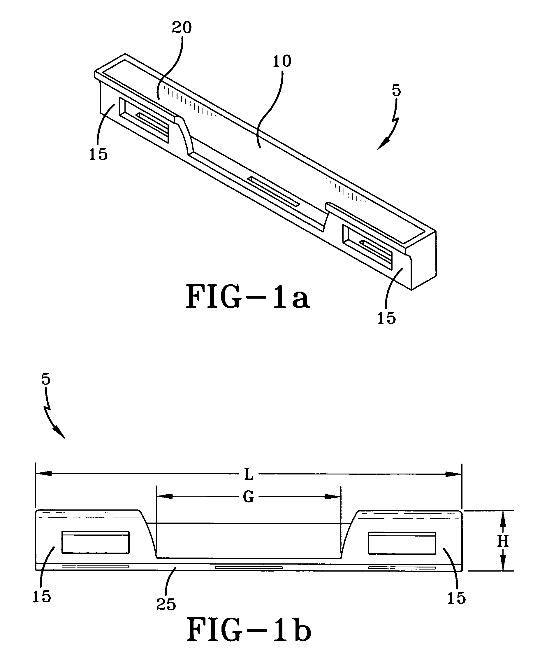
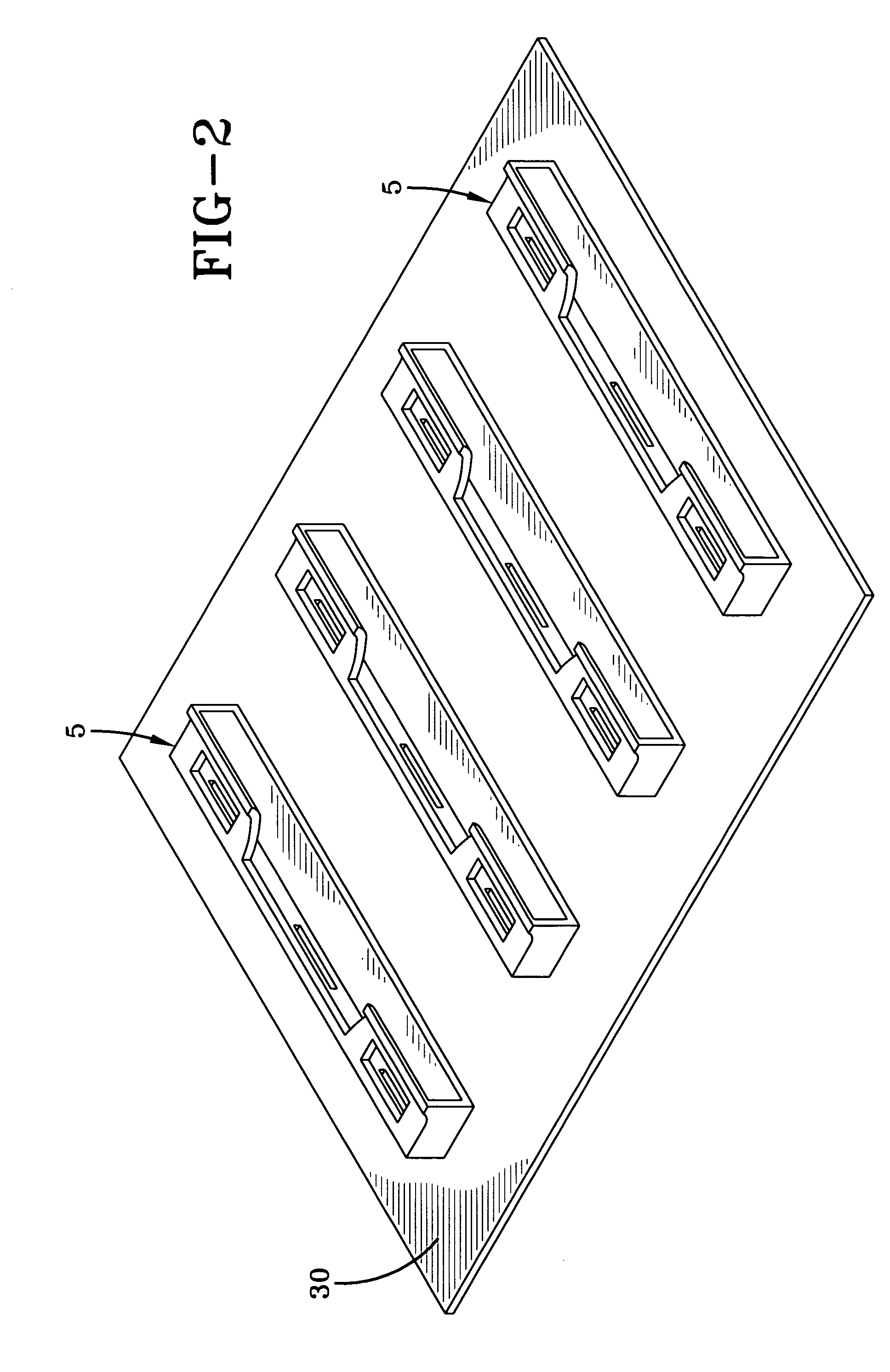
[0029]An exemplary trim clip that may be operated upon by the tool and process of the present invention is shown in FIGS. 1–2. While the trim clip 5 shown is used to retain a windshield trim piece to the vehicle once the windshield glass has been installed, it should be realized by one skilled in the art that other similar trim clips may also be installed using a tool and process of the present invention.

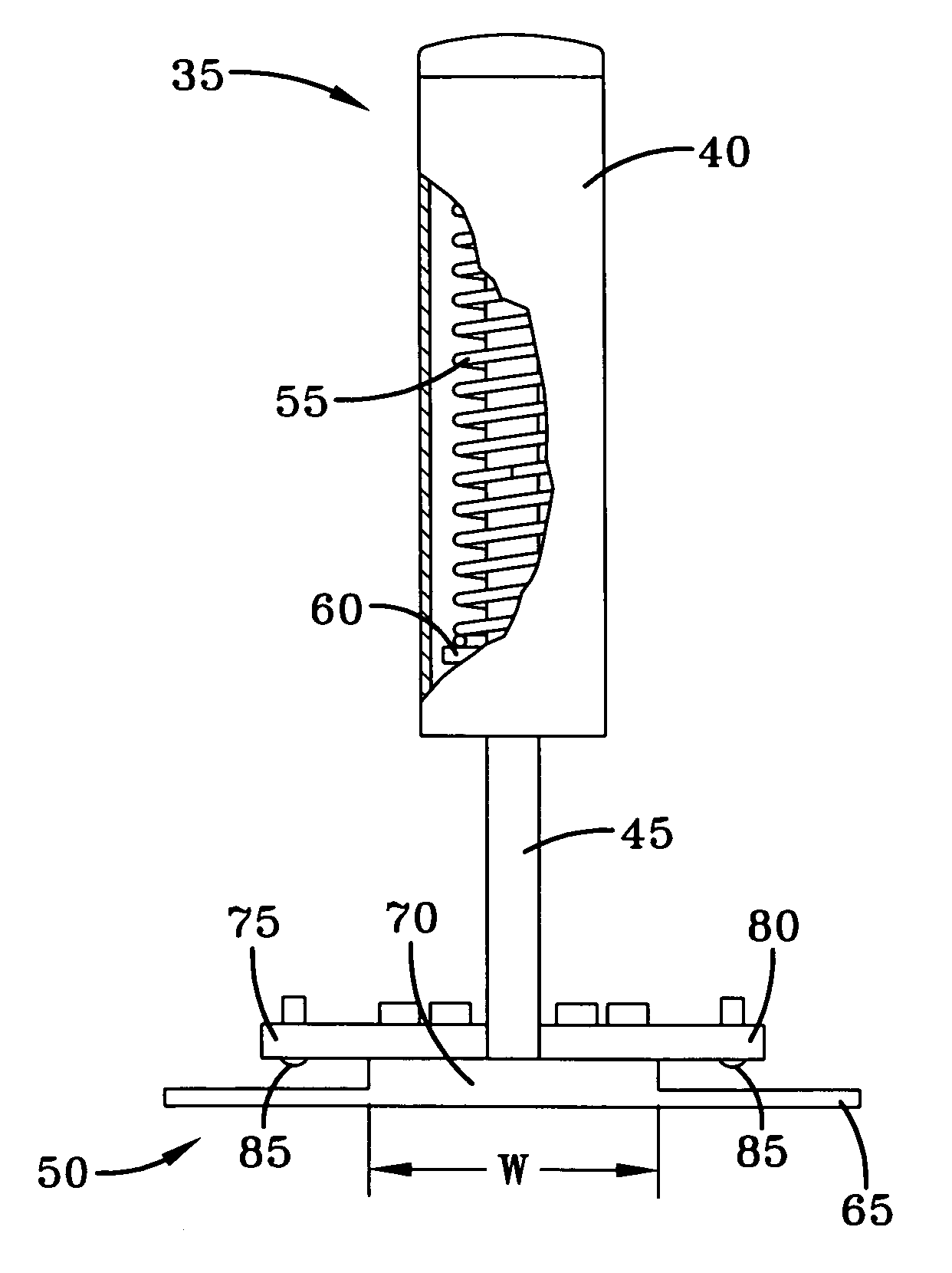
[0030]Referring particularly to FIGS. 1a–1b, it can be observed that the trim clip 5 i...


PUM

PropertyMeasurementUnit
Lengthaaaaaaaaaa
Forceaaaaaaaaaa

Abstract

A tool and process for installing a trim clip to a mounting surface. The tool includes a handle attached to a grasping portion. The grasping portion is provided with a base that is adapted for insertion into a hollow pocket that exists within the trim clip. A pair of retaining arms are maintained at some distance above the base and extend outwardly along the length thereof. The retaining arms each include at least one spring-loaded ball that extends downward from an underside thereof. When the grasping portion is engaged with the trim clip, the trim clip is retained by the presence of the base within the pocket and by a downward force exerted on the trim clip by the spring-loaded balls. The tool can be used to easily remove a trim clip from a storage medium, install the trim clip to a mounting surface, and subsequently release the trim clip.

Description

BACKGROUND OF THE INVENTION[0001]The present invention is directed to a tool and process for installing a trim clip to a mounting surface. More particularly, the present invention is directed to a tool and process for ergonomically and cleanly transferring a trim clip from a storage element to the flange of a vehicle windshield and ensuring the melt clip is sufficiently seated thereto.[0002]Trim clips can be used to attach a variety of trim pieces to different mounting surfaces, such as to different parts of a vehicle. Such clips are often installed to a vehicle at some point fairly early in the assembly process, such that they are present on the vehicle prior to the time the vehicle is subjected to a primer and or paint process.[0003]Trim clips may also be attached to a vehicle by a number of methods. For example, such clips may have protruding portions that are designed to engage a receptacle on the vehicle. Commonly, however, such clips are attached to a vehicle by some form of a...

Claims


Application Information

Patent Timeline
IPC IPC(8): B23P11/00
CPCB25B31/00B25B33/00B60R13/04B60R13/0206Y10T29/53783Y10T29/53943
Inventor LINDSEY, PAULASTRICKLAND, KENNETH E.ATSUTA, SHINICHIWHEELER, ROBERT JOHNPERECMAN, JACK LEON
Owner HONDA MOTOR CO LTD
Why Eureka
Try Eureka