
Connector equipped with a valve

a technology of connecting rods and valves, which is applied in the direction of functional valve types, machines/engines, couplings, etc., can solve the problems of less efficient production of connectors equipped with valves, difficult to provide the necessary flow, and complicated production of connectors, etc., to achieve efficient production and large flow

Active Publication Date: 2007-05-29
HONDA MOTOR CO LTD
View PDF10 Cites 14 Cited by
  • Summary
  • Abstract
  • Description
  • Claims
  • Application Information

AI Technical Summary

Benefits of technology

[0020]The object of the present invention is to provide a connector equipped with a valve that can provide a large flow when the valve is open and also can be efficiently produced.
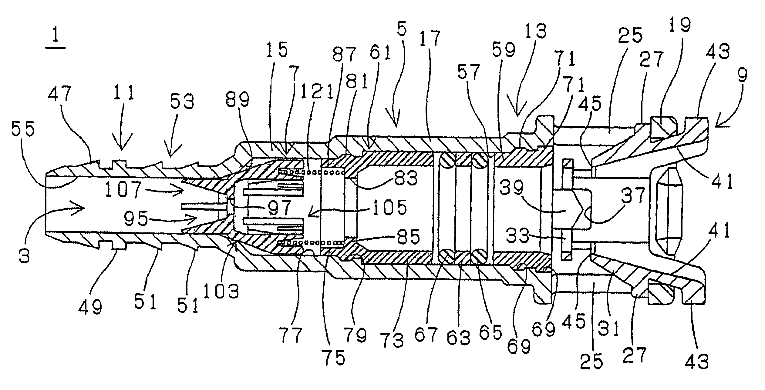
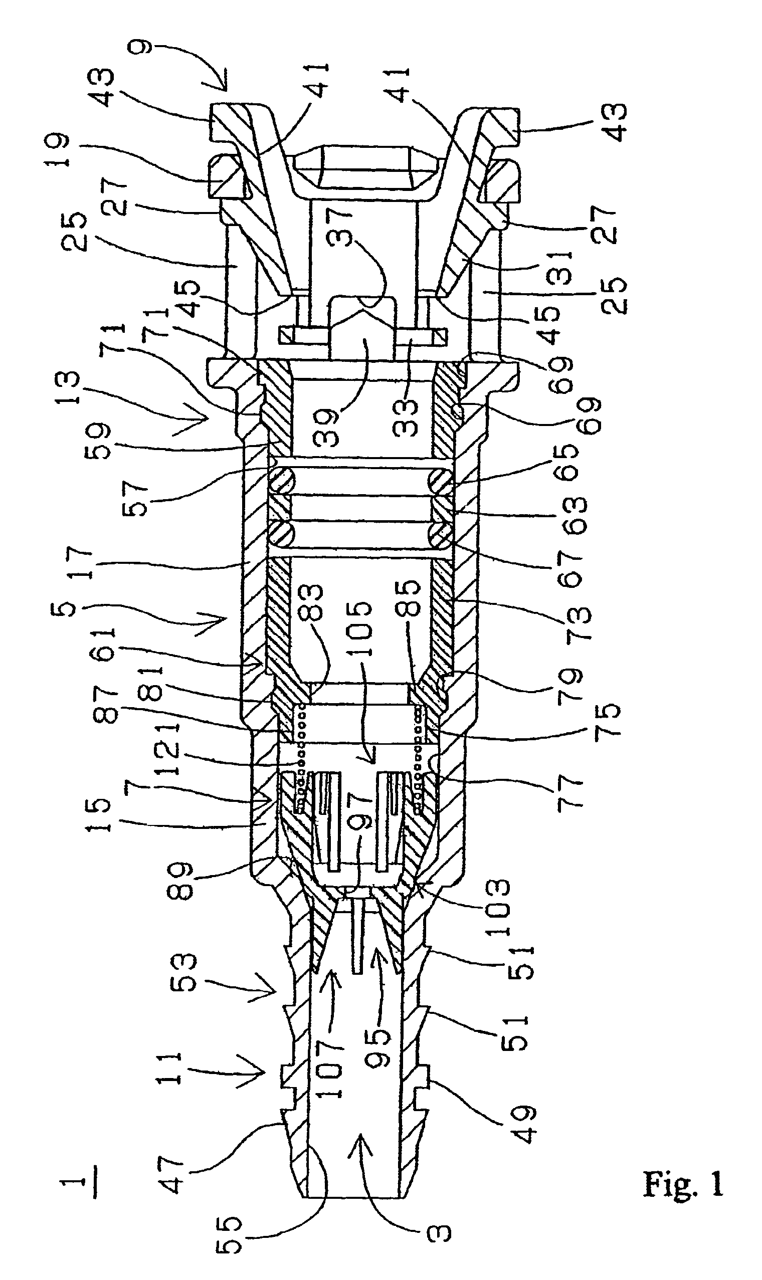
[0021]The present invention provides a connector equipped with a valve including a connector housing with a through path, a tube connection section being formed at a first axial side and a pipe insertion section being formed at a second axial side; and an internal valve disposed in the connector housing to open and close the through path. The connector housing includes a valve housing section disposed between the tube connection section and the pipe insertion section, an inner diameter of the valve housing section is larger than an inner diameter of the tube connection section. The internal valve includes a valve seat surface formed at an inner surface of the housing between the tube connection section and the valve housing section; a closing section with an outer perimeter section on which is formed an abutting surface abutting the valve seat surface; a main valve body housed in the valve housing section to allow axial movement. A compression spring biases the main valve body toward a first axial side. A cylindrical bushing is fitted to the pipe insertion section to fill space between an inner perimeter surface of a first axial side of the pipe insertion section and an insertion-side end of an inserted pipe body. Since the valve seat surface is formed on the inner housing surface, the accuracy of valve functions is essentially dependent only on the precision of the dimensions of connector housing and the main valve body. Thus, a connector equipped with a valve can be produced efficiently.
[0022]As a result, a valve seat surface having a diameter larger than that of the through-path of the tube connection section can be formed, and a large-diameter abutting surface that abuts the valve seat surface can use a large-diameter main valve body having a closing section formed on the outer perimeter section. As a result, when the valve is open a large flow can be provided.
[0025]The first axial end of the compression spring can be held and supported in a support groove formed at a second axial side or end of the housing-side guide. This allows the compression spring to be formed with a large diameter and prevents the narrowing of the flow path when the spring receiving section is formed to receive the second axial end of the compression spring.
[0027]The valve seat surface can be formed with a linear cross-section shape, and the abutting surface of the closing section can be formed with an arc projecting outward as seen from the cross-section. Thus, can contact between the valve seat surface and the abutting surface of the closing section take place along a line to provide a reliable flow blocking function when the valve is closed.

Problems solved by technology

This restriction makes it difficult to provide the necessary flow when the flow path is open.
Thus, the production of the connector equipped with a valve becomes complicated.
This makes the connector less efficient to produce.

Method used


Image

  • Connector equipped with a valve
  • Connector equipped with a valve
  • Connector equipped with a valve

Examples


Embodiment Construction

[0029]The embodiments of the present invention will be described using FIG. 1 through FIG. 7.

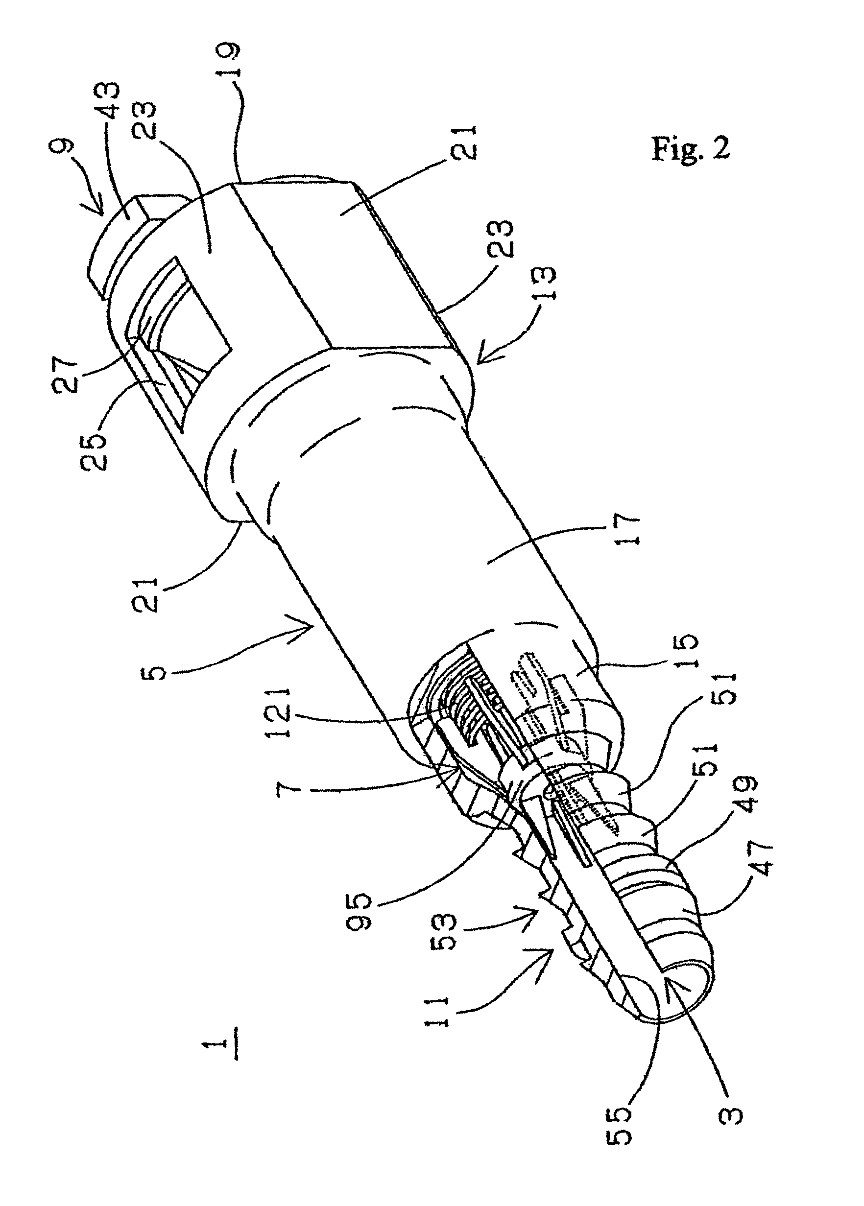
[0030]FIG. 1 is a cross-sectional view of a connector with internal valve according to the present invention. FIG. 2 is a partially cut-away perspective view of a connector with internal valve.

[0031]A connector with internal valve 1 used, for example, with evaporation tubing for gasoline fuel tank, includes a connector housing 5 formed with a through-path 3 in the axial direction and can be made from a glass fiber reinforced polyamide (PA / GF-, e.g., a glass fiber reinforced nylon 6). An internal check valve 7 is fitted inside the connector housing 5; and a retainer 9 is fitted to the connector housing 5 and can also be made from PA, (e.g., nylon 6 / 12). The connector housing 5 can be integrally formed and includes: a tube connecting section 11 formed with a small diameter at a first axial end thereof; a pipe insertion section 13 at a second axial end; and a valve housing section 15 interposed...


PUM


Abstract

A connector housing of a valve-equipped connector is integrally formed from a tube connection section at a first axial side; a pipe insertion section at a second axial side; and a valve housing section between the tube connection section and the pipe insertion section. The valve housing section is formed with an adequately large inner diameter. A main valve body and a compression coil spring for biasing the main valve body to the first axial side so that it abuts the inner surface of the housing are stored in the valve housing section. A cylindrical bushing is fitted to the first axial side of the pipe insertion section of the connector housing, and a valve cap for receiving a second axial end of the compression coil spring is formed integrally at the first axial end of the cylindrical bushing.

Description

BACKGROUND OF THE INVENTION[0001]1. Field of the Invention[0002]The present invention relates to a connector equipped with a valve such as those used for evaporation tubes in fuel supply systems of automobiles.[0003]2. Discussion of the Related Art[0004]In order to prevent fuel vapor gas generated in gasoline fuel tanks of automobiles from being discharged into the atmosphere, a vapor discharge prevention mechanism that causes the vapor to be adsorbed in the canister is widely used. In this type of vapor discharge prevention mechanism, the evaporation tube connecting the fuel tank and the canister uses a one-way or check valve to maintain an appropriate pressure in the fuel tank.[0005]In this type of evaporation tube, rubber hoses are connected to the ends of the one-way valve or check valve. The end of the rubber hose on a first side is connected, e.g., to a connecting pipe connected to a roll-over valve disposed on the fuel tank. A second end of the rubber hose on a second side is...

Claims


Application Information

Patent Timeline
Patent Type & Authority Patents(United States)
IPC IPC(8): F16K15/02F16L29/00F02M37/00F02M25/08F16K17/08F16L37/12F16L37/40F16L37/46
CPCF16K15/026F16K17/082F16L37/40Y10T137/7854Y10T137/7939Y10T137/7847Y10T137/7856F16K15/063
Inventor MIYAJIMA, ATSUO
Owner HONDA MOTOR CO LTD
Learn More