
Rear wheel synchronous brake system for pushcart

Inactive Publication Date: 2007-05-29
LIU SSU LIU
View PDF9 Cites 23 Cited by
  • Summary
  • Abstract
  • Description
  • Claims
  • Application Information

AI Technical Summary

Benefits of technology

[0001]The present invention relates to a pushcart and more specifically, to a rear wheel synchronous brake system for pushcart that can conveniently be operated to synchronously stop the two rear wheels of the pushcart. The present invention is practical for use in a push card having a front flywheel.
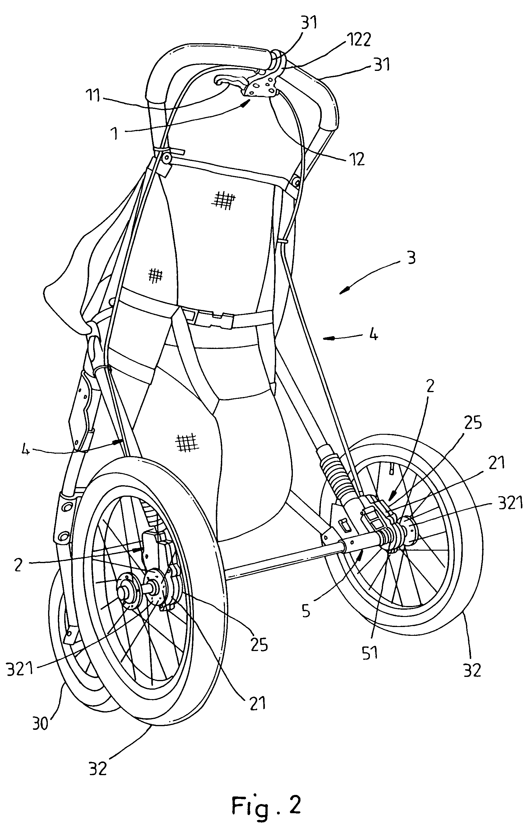
[0003]The present invention has been accomplished under the circumstances in view. It is therefore one object of the present invention to provide a rear wheel synchronous brake system for pushcart, which is convenient to operate. It is another object of the present invention to provide a rear wheel synchronous brake system for pushcart, which is safe in use. It is still another object of the present invention to provide a rear wheel synchronous brake system for pushcart, which is suitable for use in a pushcart that has a front flywheel. To achieve these and other objects of the present invention, the rear wheel synchronous brake system comprises two rear brakes respectively coupled to the two rear wheels of the baby jogging stroller, a hand control unit mounted on the handle of the baby jogging stroller at the top, and two brake lines coupled between the brake lever of the hand control unit and the two rear brakes for driving the rear brakes to brake the two rear wheels of the baby jogging stroller synchronously when the user pulling the brake lever. When the user pulling the brake lever, the steel wires of the two brake lines are driven to move the rear brakes synchronously, thereby causing the rear brakes to brake the two rear wheels of the baby jogging stroller. On the contrary, when the user released the hand from the brake lever, the rear brakes are reversed by respective torsional springs to move the respective brake shoes away from the rear wheels. Because the brake system is operable by the hand control unit through the hand-operated brake lever, the brake system assures high safeness. The user can pull the brake lever with the hand to stop the cart instantly upon occurrence of an unexpected sudden condition during jogging.BRIEF DESCRIPTION OF THE DRAWING

Problems solved by technology

It is inconvenient and dangerous to operate this brake system when jogging.

Method used


Image

  • Rear wheel synchronous brake system for pushcart
  • Rear wheel synchronous brake system for pushcart
  • Rear wheel synchronous brake system for pushcart

Examples


Embodiment Construction

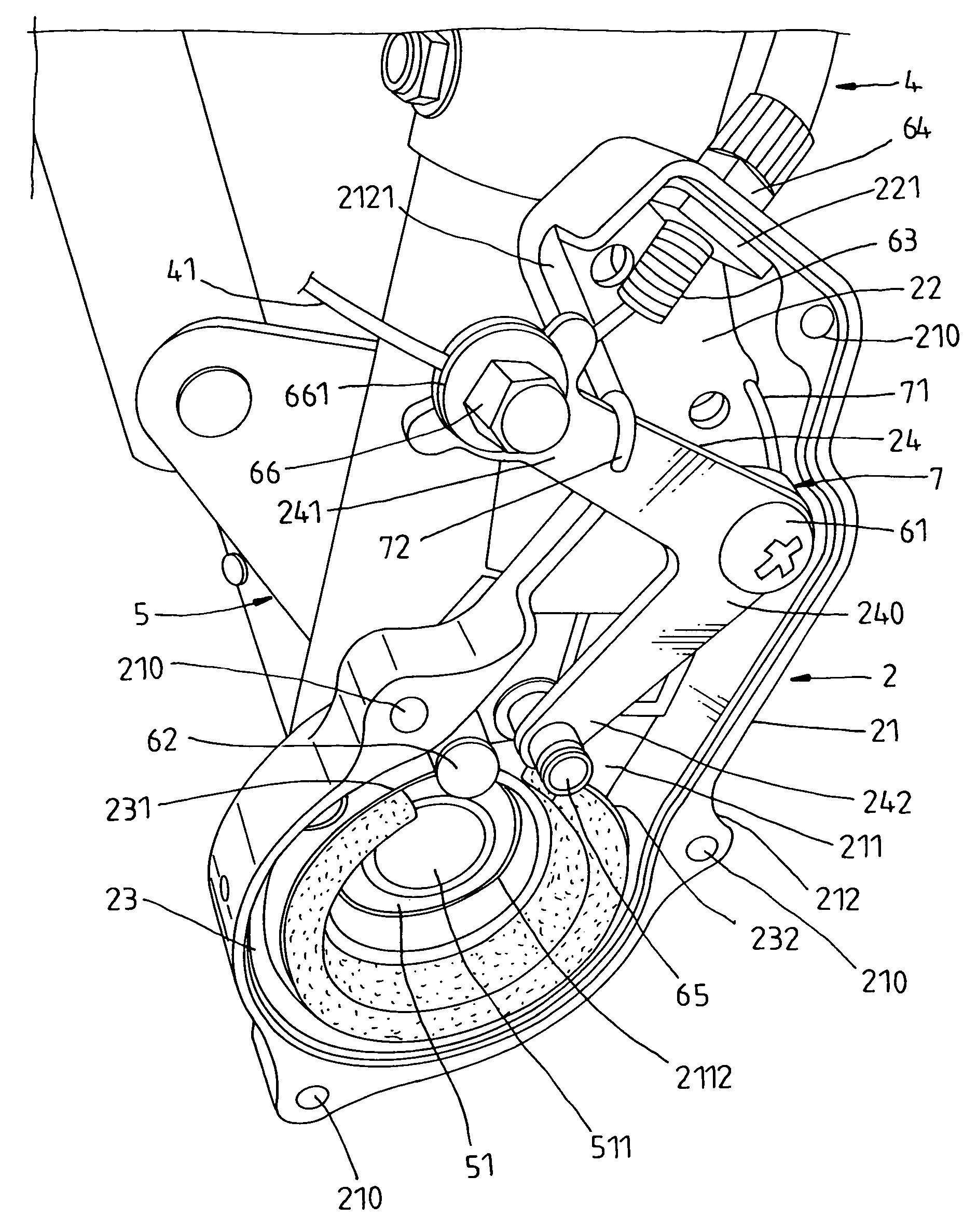
[0024]Referring to FIGS. 2 and 3, a rear wheel synchronous brake system is shown used in a pushcart. According to this embodiment, the pushcart is a baby jogging stroller. The baby jogging stroller 3 comprises a front wheel 30, and two rear wheels 32. The rear wheel synchronous brake system comprises a hand control unit 1 and two rear brakes 2. The hand control unit 1 is installed in the handle 31 of the baby jogging stroller 3 at the top side. The hand control unit 1 comprises a brake lever 11 and two brake lines 4. The respective steel wires 41 of the brake lines 4 are respectively connected to the rear brakes 2. When the user pulls the brake lever 11, the steel wires 41 of the brake lines 4 are driven to move the rear brakes 2 against the rear wheels 32 respectively, thereby stopping the rear wheels 32. The rear wheels 32 have the respective hub 321 respectively mounted with a respective wheel axle 3211, which is supported in an axle hole 511 in an axle holder 51 at one end of a ...


PUM


Abstract

A rear wheel synchronous brake system used in a pushcart such as a baby jogging stroller is disclosed to include two rear brakes respectively coupled to the two rear wheels of the baby jogging stroller, a hand control unit mounted on the handle of the baby jogging stroller at the top, and two brake lines coupled between the brake lever of the hand control unit and the two rear brakes for driving the rear brakes to brake the two rear wheels of the baby jogging stroller synchronously when the user pulling the brake lever.

Description

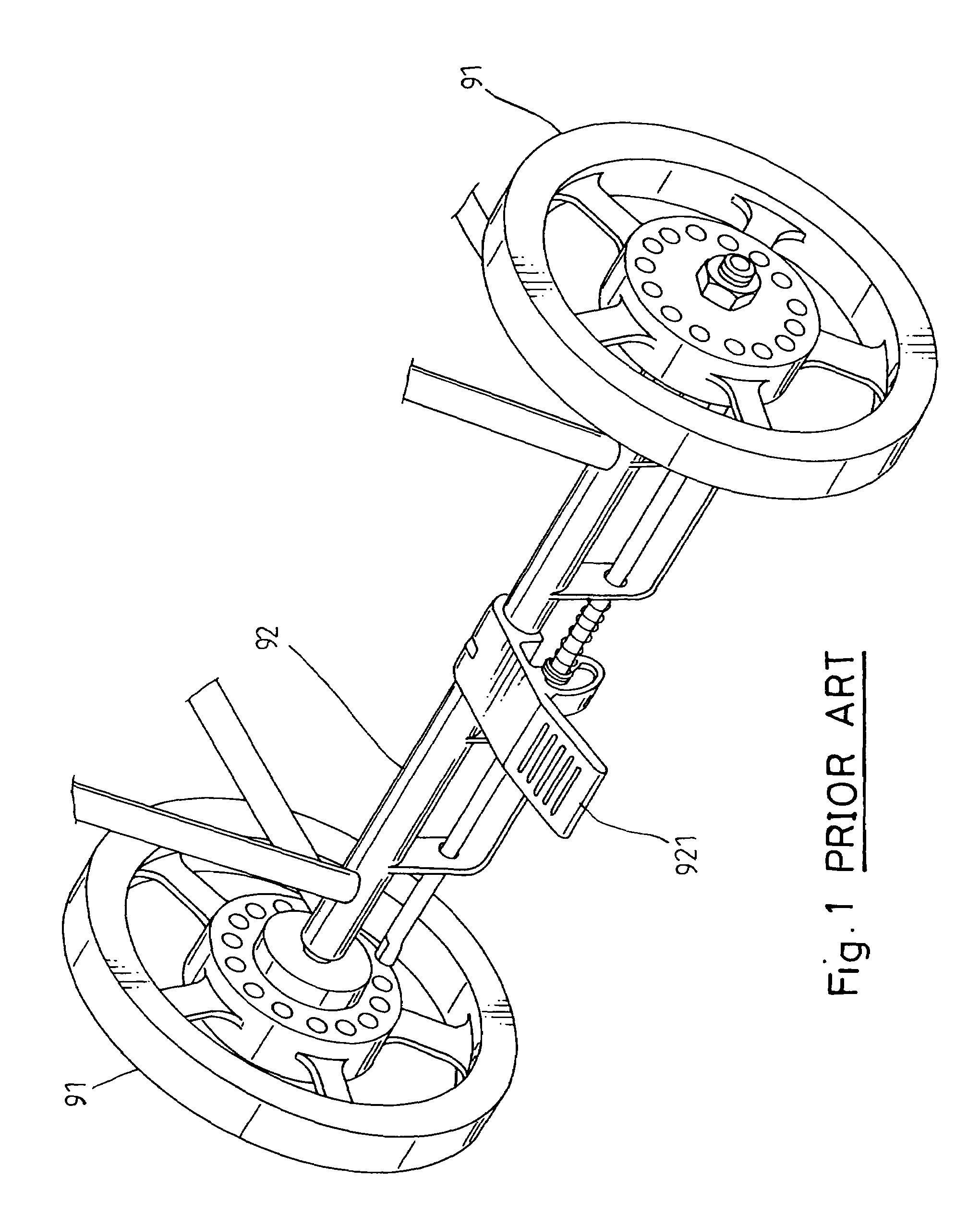
BACKGROUND AND SUMMARY OF THE INVENTION[0001]The present invention relates to a pushcart and more specifically, to a rear wheel synchronous brake system for pushcart that can conveniently be operated to synchronously stop the two rear wheels of the pushcart. The present invention is practical for use in a push card having a front flywheel.[0002]A baby jogging stroller or baby stroller has at least one front wheel and two rear wheels. A baby jogging stroller is designed to carry a baby or young child for pushing by a person who is jogging. A baby stroller is a small carriage in which a baby or child is pushed around. A regular three-wheel type baby cart includes one front wheel and two rear wheels. The front wheel is a flywheel. A baby cart of this design must have the brake system set to stop the rear wheels. FIG. 1 shows a brake system used in a baby jogging stroller. According to this design, the brake system 92 has a brake pedal 921 for pressing by leg to stop the two rear wheels...

Claims


Application Information

Patent Timeline
IPC IPC(8): B62B9/00B60T1/00B62B3/00B62B5/04B62B9/08B62L3/00
CPCB60T7/102B62L3/02F16D51/02F16D51/04F16D65/14B62B9/082B62B9/085B62B9/087B62B5/0438B62B5/048F16D2121/14F16D2125/64
Inventor LIU, SSU-LIU
Owner LIU SSU LIU
Learn More