Cable connector incorporating anisotropically conductive elastomer

a technology of anisotropic conductive elastomer and cable connector, which is applied in the direction of elastomeric connection elements, coupling device connections, connection contact member materials, etc., can solve the problems of slow maximum signal transfer speed, large volume of connectors, and incremental increase in resistance/impedance of signal paths, etc., to achieve easy separability of cable connectors and high speed. , the effect of high speed

Inactive Publication Date: 2007-05-29
PARICON TECH
View PDF20 Cites 90 Cited by
  • Summary
  • Abstract
  • Description
  • Claims
  • Application Information

AI Technical Summary

Benefits of technology

[0006]It is therefore an object of this invention to provide an extremely high speed, easily separable cable connector.
[0007]This invention results from the realization that high speed, simple to use cable termination connectors can be accomplished with a layer of ACE compressed between the cable end and the electrical device to which the cable is being conductively interconnected.

Problems solved by technology

However, these connectors are relatively bulky and expensive, and require the additional steps of connecting the connectors to the end of the cable and to the printed circuit board.
Another problem with such connectors is that the combination mechanical and electrical connection between each of the connectors of the cable and the terminating connector, the connection between the connectors themselves, and the connection of the connector to the printed circuit board, each add incrementally to the resistance / impedance of the signal path, resulting in slower maximum signal transfer speeds and increased power dissipation.
Further, these connectors are relatively difficult to couple and decouple; most times these operations require human intervention.

Method used


Image

  • Cable connector incorporating anisotropically conductive elastomer
  • Cable connector incorporating anisotropically conductive elastomer
  • Cable connector incorporating anisotropically conductive elastomer

Examples


Embodiment Construction

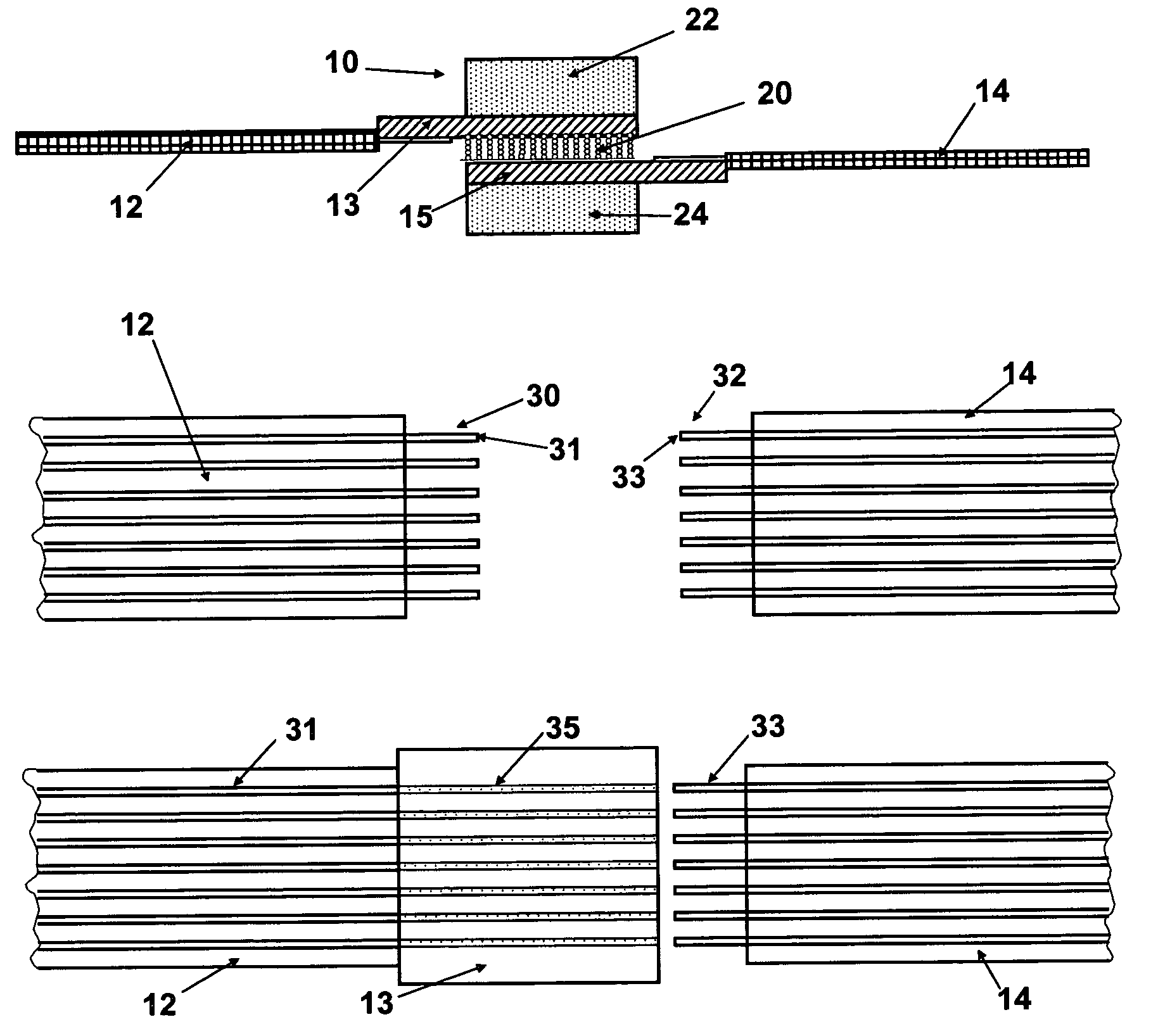
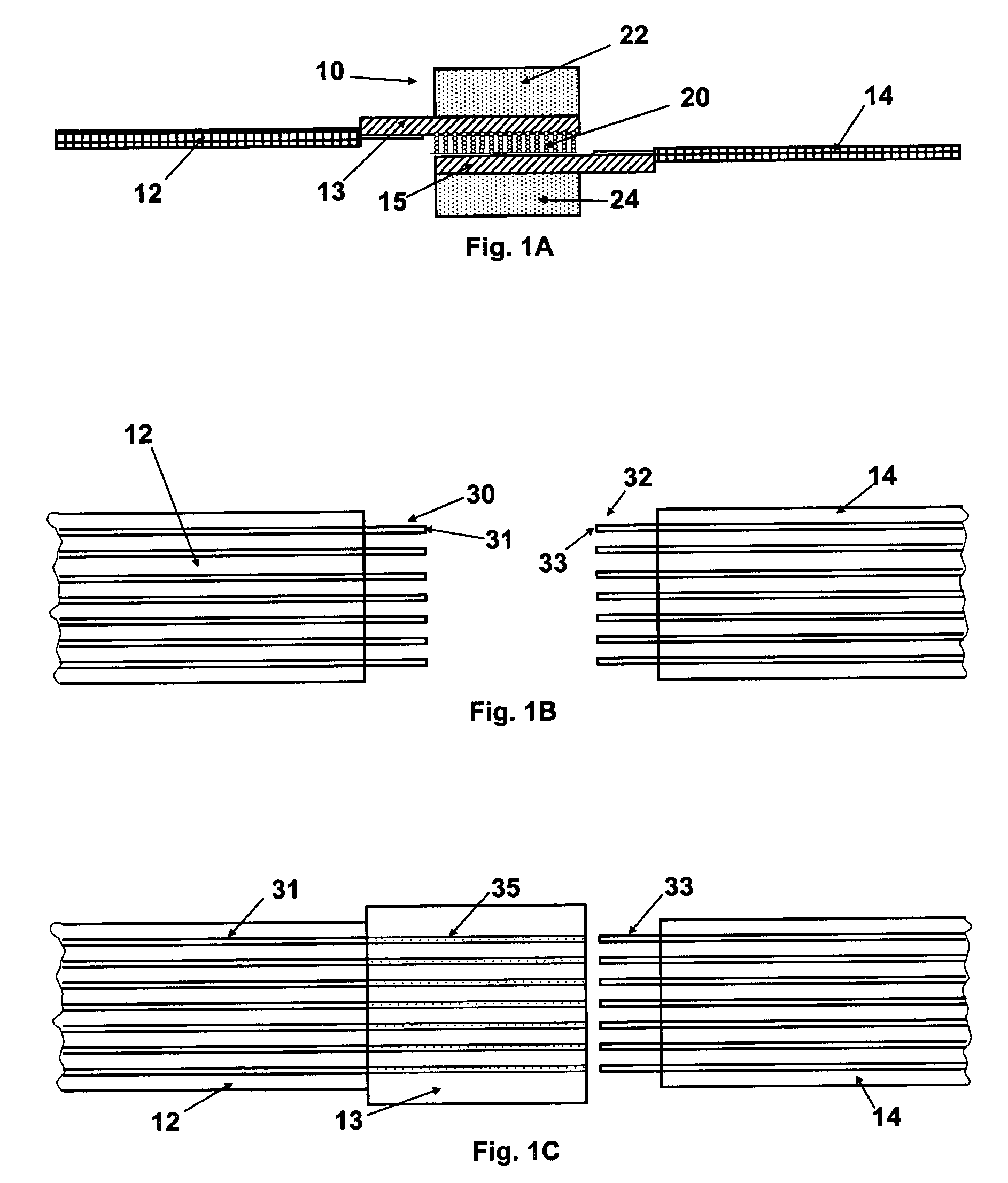
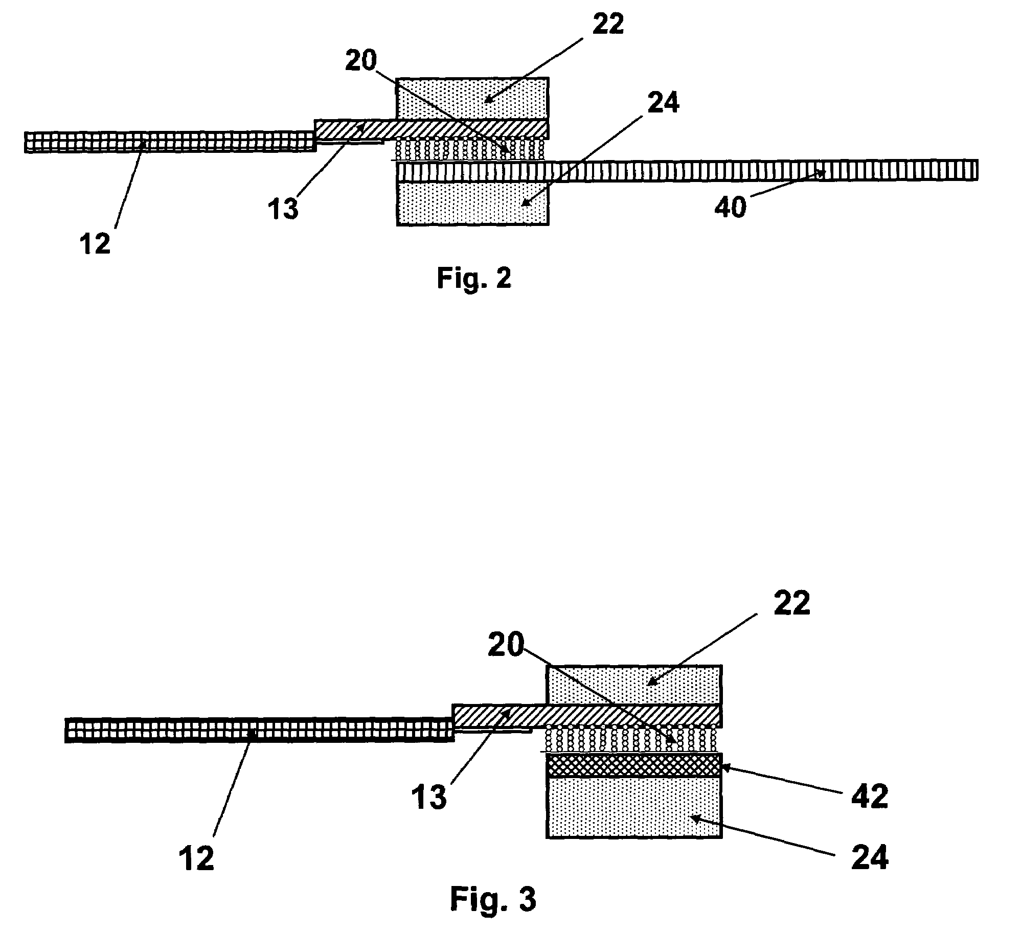
[0024]FIG. 1 presents a preferred embodiment of this invention as applied to a ribbon cable to ribbon cable interconnection. Connector 10 interconnects conductor set 30 of ribbon cable 12 to conductor set 32 of ribbon cable 14. In this embodiment, each ribbon cable 12, 14 is terminated to a small circuit board (paddle board) 13, 15, respectively. Boards 13 and 15 include surface conductive traces such as trace 35 on board 13, FIG. 1C. These surface traces are functionally stiffer, properly spaced (registered) continuations of the conductors of the ribbon cables. The circuitry on the circuit board is preferably arranged to optimize the functionality of interconnect 10. Ground planes and controlled impedance lines can be employed for high-speed interconnection. Circuit boards 13 and 15 are aligned to each other, and electrically interconnected by ACE layer 20. Clamp members 22, 24 are urged toward one another (for example using bolts) to provide the alignment between the conductors of...


PUM


Abstract

A separable electrical connector for separably, electrically interconnecting the conductors of one multi-conductor cable to the conductors of a second electrical device that may be an electrical device such as a chip, or a second multi-conductor cable, or a flexible or rigid printed circuit board. The connector includes a layer of anisotropic conductive elastomer (ACE) in electrical contact with the conductors of the cable and the conductors of the second electrical device. A clamp or another type of mechanical device compresses the ACE, to provide electrical signal paths between the conductors of the cable and the second electrical device, through the ACE.

Description

CROSS REFERENCE TO RELATED APPLICATION[0001]This application is a continuation in part of application Ser. No. 09 / 465,056, entitled “Elastomeric Interconnection Device and Methods for Making Same” filed on Dec. 16, 1999 now U.S. Pat. No. 6,854,985. Priority is claimed.FIELD OF THE INVENTION[0002]This invention relates to separable cable connectors with advanced electrical performance.BACKGROUND OF THE INVENTION[0003]Electrical cables are typically connected to devices such as printed circuit boards using pin-type connectors that terminate the cable and fit into a connector having a complementary shape permanently mounted to the electrical device. Cable-to-cable connectors are accomplished in a similar fashion. However, these connectors are relatively bulky and expensive, and require the additional steps of connecting the connectors to the end of the cable and to the printed circuit board.[0004]Another problem with such connectors is that the combination mechanical and electrical con...

Claims


Application Information

Patent Timeline
Patent Type & Authority Patents(United States)
IPC IPC(8): H01R12/00H01R4/26H01R13/24H01R43/00
CPCH01R13/2414H01R4/26H01R43/007H01R2201/20
Inventor WEISS, ROGER E.BARNUM, DAVID M.
Owner PARICON TECH
Why Eureka
Try Eureka