
Method, dielectric element, and MR system for generating an MR exposure

a dielectric element and exposure technology, applied in the field of dielectric element and mr system for generating an mr exposure, can solve problems such as interference effects, and achieve the effect of reducing or even completely preventing interference in magnetic resonance exposures

Active Publication Date: 2007-05-29
SIEMENS HEALTHCARE GMBH
View PDF7 Cites 2 Cited by
  • Summary
  • Abstract
  • Description
  • Claims
  • Application Information

AI Technical Summary

Benefits of technology

[0009]An object of the present invention is to provide a method for generating magnetic resonance exposures using dielectric elements as well as a dielectric element and a corresponding magnetic resonance system for implementation of such a method, wherein interferences in the magnetic resonance exposures are reduced or even entirely prevented in a simple manner by the positioned dielectric elements.
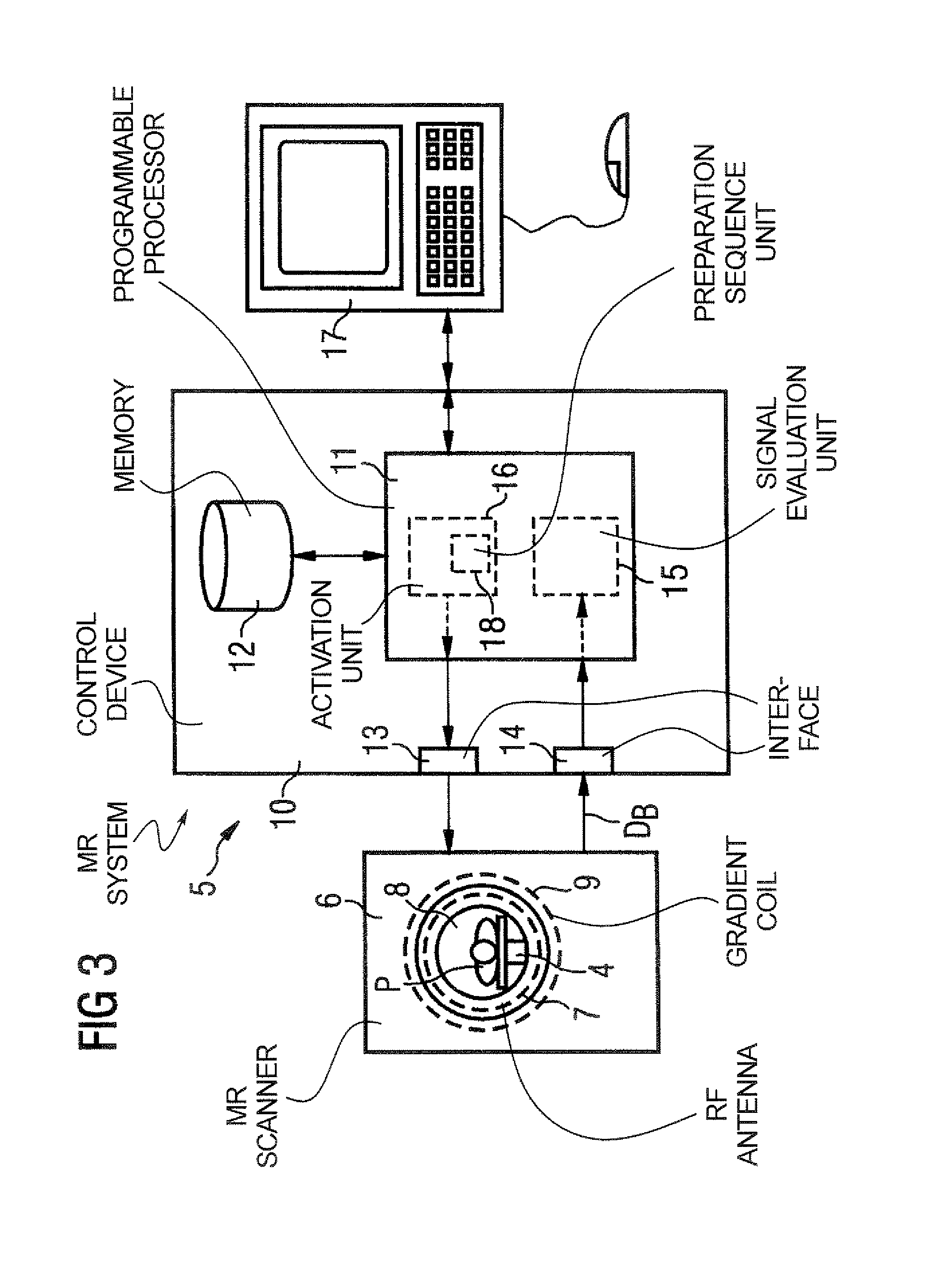
[0016]Since typical magnetic resonance systems include a programmable control device anyway, the inventive control device preferably is realized by suitable control software in such a programmable control device. This means that a computer program product is loaded into the memory of the programmable control device of the appertaining magnetic resonance system, the computer program product includes a program code in order to activate the radio-frequency antenna and the gradient coils for the emission of the desired measurement sequences according to the inventive method. This software embodiment has the advantage that existing magnetic resonance systems or existing control devices can be upgraded in a simple manner at any time, such that the inventive method can be used together with the use of the inventive dielectric elements.
[0029]A further possibility to separate the signals caused by the dielectric material of the dielectric element from the signals caused by the examination subject is the use of a method known as the echo-time encoding method (Dixon method). In this measurement method, the spectroscopic information is coded in an additional dimension. In contrast to a real four-dimensional imaging, in which three dimensions reproduce the spatial information and one dimension reproduces the spectroscopic information, as with a normal imaging the raw image data are acquired with an applied readout gradient, and the spectral information are acquired by an incremented temporal shifting of the echo position. This means that, by deliberately separating the spin-echo and the gradient-echo conditions, a separation ensues of the desired imaging signal from the signals of the material that should not be visible. An advantage of this method is that the number of the increments determines the spectroscopic resolution. In the extreme case—given only two magnetic resonance lines in the spectrum—the number of the increments is reduced to two. A combination of both of the acquired data sets allows the generation of various images that essentially represent only the desired species. The method is based on evolution intervals whose duration is selected such that the protons of the desired species directly establish a phase difference of 180° relative to the unwanted species. Normally, however, it is always necessary to acquire at least two images and to separate the individual images of both atomic species from one another by suitable post-processing. The measurement time is thereby extended by at least a factor of 2.

Problems solved by technology

This means that all significant parts of the dielectric element which could lead to larger interfering effects in the image are composed of such a dielectric material.

Method used


Image

  • Method, dielectric element, and MR system for generating an MR exposure
  • Method, dielectric element, and MR system for generating an MR exposure
  • Method, dielectric element, and MR system for generating an MR exposure

Examples


Embodiment Construction

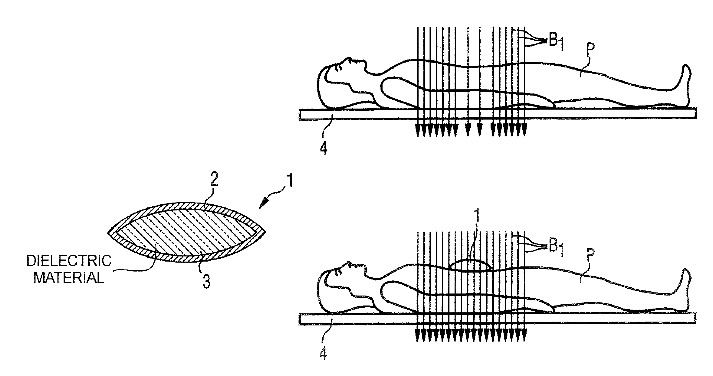
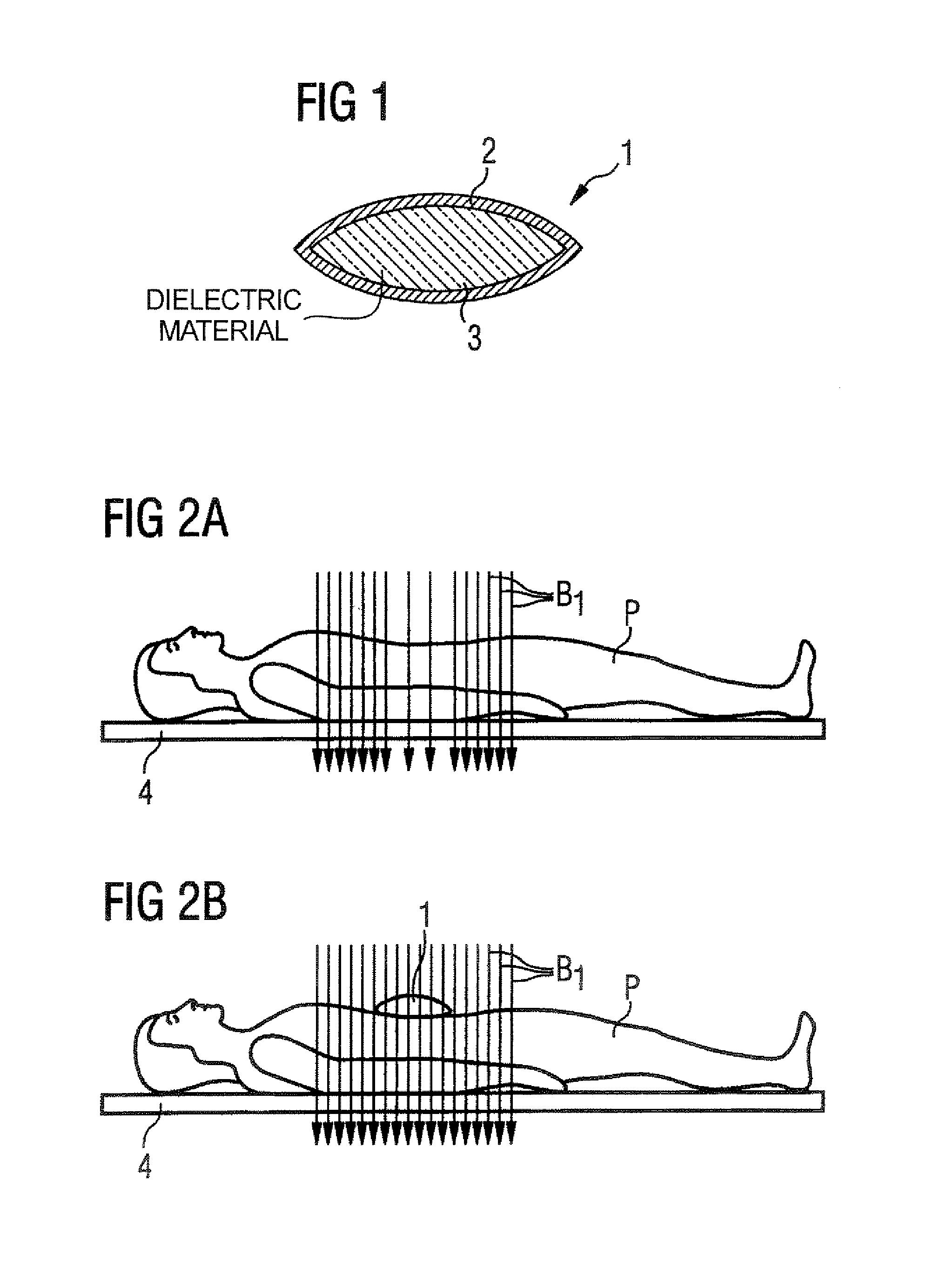
[0035]The dielectric element shown in FIG. 1 is a dielectric pillow 1, formed of an outer jacket made of plastic film 2 and a filler of dielectric material 3. The plastic film 2 is a bio-compatible material that is relatively thin but nevertheless is sufficiently stable to prevent leakage of the dielectric material 3 contained therein. The plastic film 2 preferably is fused all around the periphery of the dielectric pillow 1.

[0036]In addition, the dielectric pillow 1 in use can be covered with a washable pillowcase which can be changed before usage of the dielectric pillow 1 on another patient. The plastic jacket 2 can be disinfected with typical means.

[0037]The filling of the dielectric pillow 1, i.e. the dielectric material 3 of which the dielectric element 1 is essentially formed, exhibits only magnetic resonance lines that are shifted by a specific degree relative to the magnetic resonance line of water protons given a given magnetic field.

[0038]The concrete exemplary embodiment...


PUM


Abstract

For generating of magnetic resonance exposures of an examination subject, a dielectric element with high dielectric constant is positioned on the examination subject to locally influence the B1 field distribution, the dielectric element being formed primarily of material whose magnetic resonance line(s) is / are shifted by at least a specific degree relative to the magnetic resonance line of water protons for a given magnetic field. In a measurement for generation of a magnetic resonance exposure a measurement sequence is used, such in the acquisition of the raw image data the dielectric material of the dielectric element supplies no signal contributions for the image generation and / or the signals caused by the dielectric material of the dielectric element can be separated from the signals caused by the examination subject.

Description

BACKGROUND OF THE INVENTION[0001]1. Field of the Invention[0002]The present invention concerns a method for generating magnetic resonance exposures (i.e. acquiring magnetic resonance data) of an examination subject, of the type wherein a dielectric element with high dielectric constant is positioned on the examination subject to locally influence the B1 field distribution. Moreover, the invention concerns a corresponding dielectric element for positioning on an examination subject for locally influencing the B1 field distribution during magnetic resonance data acquisition and a corresponding magnetic resonance system for implementation of the method.[0003]2. Description of the Prior Art[0004]Magnetic resonance tomography has become a widespread technique for the acquisition of images of the inside of the body of a living examination subject. In order to acquire an image with this method, i.e. to generate a magnetic resonance exposure of an examination subject, the body or a body par...

Claims


Application Information

Patent Timeline
Patent Type & Authority Patents(United States)
IPC IPC(8): G01V3/00G01R33/36G01R33/56
CPCG01R33/5659
Inventor FEIWEIER, THORSTENKIEFER, BERTHOLDRENZ, WOLFGANGSCHON, LOTHAR
Owner SIEMENS HEALTHCARE GMBH
Learn More