Immersive imaging system

a technology of imaging system and camera, applied in the field of imaging system, can solve the problems of high power consumption, limited rotational extent, and drawbacks of the mechanism

Inactive Publication Date: 2007-05-29
IMAGE MASTERS
View PDF15 Cites 131 Cited by
  • Summary
  • Abstract
  • Description
  • Claims
  • Application Information

AI Technical Summary

Benefits of technology

[0068]It is also an advantage of the invention to support pan, tilt and digital zoom functions of the resultant stereoscopic images without moving parts in at least one embodiment of the system.
[0069]It is a further advantage of this invention to dynamically correct right-eye and left-eye views from individual camera sub-systems to re-establish average interpupillary separation distances, providing a seamless panorama with consistent stereopsis effects.
[0070]Another advantage of the invention is that it performs distance measurement analyses of such stereoscopic images so as to provide distance and direction figures-of-merit for use by viewing individuals or analytical processes.
[0071]Another advantage of the invention is a predominantly monoscopic embodiment of this system with a camera head assembly that can momentarily change optical component positions to capture stereoscopic views, accomplish passive stereo distance measurements, and track moving objects, among other activities, on a selective basis for a subset of the panorama.
[0072]Yet another advantage of this invention is that the camera head is optionally packaged as a reduced size model according to the principles of this invention that is useful for field applications in both military and commercial settings.
[0073]A further advantage of this invention is the ability to control pan, tilt and zoom operations through operations of software based on objects or conditions detected in the environment.

Problems solved by technology

However, there are drawbacks to that mechanism.
The motorized mechanisms of PTZ cameras have lag times associated with physical movement, high power consumption, limited rotational extents, FOV obstructions by motor and supports, maintenance and mechanical wear of moving components, and the risk of loss of calibration over time.
There is also a concern over response time, size, weight, and reliability.
Most critically, PTZ cameras can only capture the visual field where they are directly pointed at any given instant in time, limiting the usefulness of such a system for telepresent operations or viewing.
Their resolution is limited to that of the individual image sensors that are used to pick up the light, so high resolution requires high priced sensors.
The nature of a catadioptric optical system is that distortions yield a non-uniform pixel distribution across the surface of the individual imager which has an impact on the quality and subsequent extent of digital zooming and magnification of prints.
Distance measuring (ranging) is limited to estimations, which are potentially computation-intensive and prone to error.
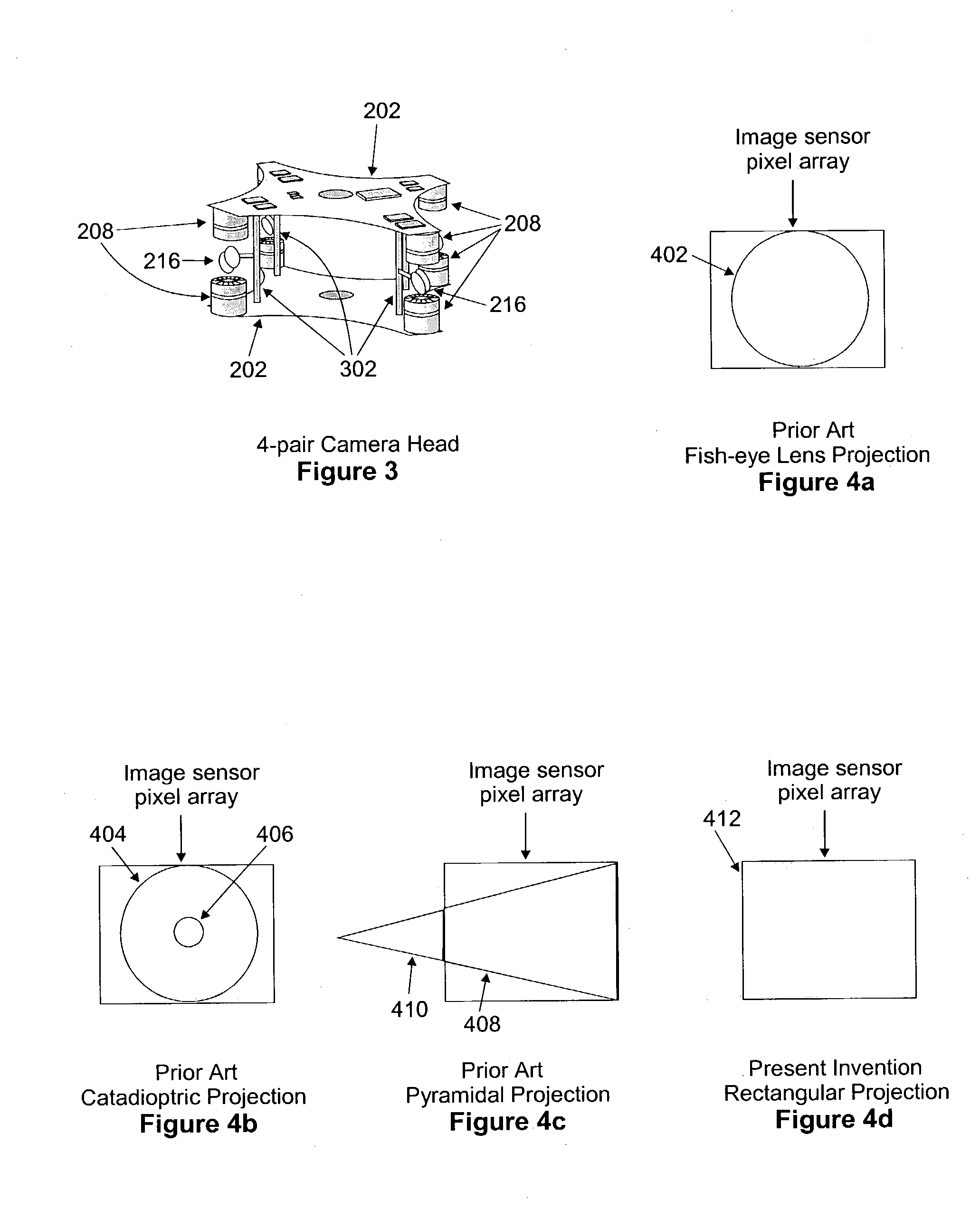
While the use of multiple sensors increases the number of image-sensing elements involved in scene capture, this method suffers from an inefficient use of image sensors, since it is not possible to fully inscribe a triangle within a square with complete coverage.
Based on its design, however, there is no practical stereoscopic video acquisition, as well as no true distance measuring.
In addition, current implementations have a large physical size and significant communication requirements.
Systems are currently only available for rent, adding to the limitations for their use in many applications.
Combining two such lenses back-to-back allows capture of almost a full spherical view but introduces image construction problems unique to the design.
: which is hereby incorporated hereinto in its entirety), for example, have edge-seaming requirements in difficult-to-seam areas (the low resolution portions of the image), fisheye effects (changing apparent depth based on direction of view), non-uniform pixel distributions over the face of the imagers, and limited resolution.
The system cannot acquire stereoscopic video in real-time.
This is a useful approach for monoscopic views of an environment, but it is incapable of capturing full stereoscopic views or distance measurements.
Rogina's method supports high resolution and real-time stereoscopic acquisition, but the radial planar configuration of multiple imagers limits viewing of near-field subjects, requires a large number of imagers taking up a large physical space, and consumes significant communication bandwidth.
While this provides a middle ground between individual imager systems and full spherical arrays, it is expensive to produce and is not designed to independently measure distances without additional external sensors.
There is no provision, however, for stereoscopic capture or distance measurement in this radial arrangement of components.
This method does not support stereoscopy or ranging (i.e., distance measurements).
This method does not encompass full 360° panoramic acquisition, nor is it capable of stereoscopy.
This system is significantly limited in resolution and the extent of its FOV, not acquiring even 180° of visual content.
(For general information refer to U.S. Pat. No. 5,668,595) describes a different apparatus that can alternate between “panoramic” (though nowhere near 360°) and stereoscopic modes through the use of 2-imager sub-systems, but this is likewise limited in the extent of its FOV.
The method does not teach the coincident alignment of multiple imaging sub-systems through manufacturing processes to ensure inter-pixel spacing for high resolution.

Method used


Image

  • Immersive imaging system
  • Immersive imaging system
  • Immersive imaging system

Examples


Embodiment Construction

[0106]The present invention is based on the concept of acquiring and processing dual superimposed video image data sets. The acquisition of images is accomplished without moving parts by properly positioning multiple imager sub-systems and coplanar reflective elements. Operation of the system builds a data set for each of the views that a person's eyes would see if he / she were to move his / her head around at a fixed point in space. In preparation for transmission, the video image data from each of the imager sub-systems is processed through several operations while in the camera head. The data is reversed, preferably corrected for distortions and aberrations, compressed, transmitted from the camera head to a processing unit (preferably with data compression), merged into a continuous data set, then viewed on monitors. A monoscopic version of the complete data set from either set of imagers is presented on a monitor in one of several formats based on user preferences. These formats in...


PUM


Abstract

A system, method and device for the capture and display of high-resolution stereoscopic or monoscopic wide fields-of-view (FOV) at still or video rates, presenting techniques and designs for distance measuring, for changing the working stereo capture range of a stereoscopic image capture device, and for playing pre-recorded or transmitted stereoscopic video image data through a player unit. The system supports multiple independent viewers and image analysis sub-systems of various types utilizing hardware, software and firmware. Further included is a stereoscopic videoconferencing embodiment that captures and transmits an entire room's view and automatically directs focus of images.

Description

CROSS-REFERENCED APPLICATIONS[0001]The present non-provisional application claims priority to provisional patent application Ser. No. 60 / 371,805 with inventor Robert G. Baker, entitled “Immersive Imaging System” filed Apr. 12, 2002, which is hereby incorporated by reference in its entirety.FIELD OF THE INVENTION[0002]The present invention is an imaging system that provides stereoscopic or monoscopic video acquisition, recording, playing back and transmitting the image data. Various embodiments provide adjustable stereoscopic capture ranges, analyses of image information, measurement of object distances in fields of view, and videoconferencing for 360° fields-of-view.BACKGROUND OF THE INVENTIONDefinitions:The following non-limiting definitions are used to aid the reader with this patent application.[0003]Autostereoscopic: A self-contained stereoscopic display device that supplies different views to the two eyes of a viewer without requiring additional external optical or electronic d...

Claims


Application Information

Patent Timeline
Patent Type & Authority Patents(United States)
IPC IPC(8): H04N15/00H04N13/04H04N5/225H04N5/247H04N13/00
CPCH04N5/2259H04N5/23238H04N5/247H04N13/0242H04N13/0285H04N13/243H04N13/286H04N23/58H04N23/698H04N23/90
Inventor BAKER, ROBERT G.
Owner IMAGE MASTERS
Why Eureka
Try Eureka