Low-power Booth-encoded array multiplier

a low-power, array-encoded technology, applied in the field of array-encoded array-encoded array-encoded array-encoded architecture, can solve the problems of extra hardware, complexity and delay, counter-intuitive structure, etc., and achieve the effect of reducing the number of long signal paths and reducing the switching activity of the adder array

Inactive Publication Date: 2007-05-29
RGT UNIV OF CALIFORNIA
View PDF6 Cites 2 Cited by
  • Summary
  • Abstract
  • Description
  • Claims
  • Application Information

AI Technical Summary

Benefits of technology

[0017]An advantage of an adder array configured according to the present invention is that its organization opposes the carry-propagation direction. Therefore, few signals need to propagate through the entire adder array. Another advantage is that such a structure reduces the number of long signal paths and hence reduces the switching activity in the adder array. Further advantages of the invention will be brought out in the following portions of the specification, wherein the detailed description is for the purpose of fully disclosing preferred embodiments of the invention without placing limitations thereon.

Problems solved by technology

This structure is counterintuitive because the MSD partial-products have a longer word-length and it would appear that extra hardware would be needed.
Such an adder array structure preserves the regularity and locality of a standard carry-save array, and has approximately the same complexity and delay, but with reduced power dissipation.
It obtains a different result; an error is included in the result.

Method used


Image

  • Low-power Booth-encoded array multiplier
  • Low-power Booth-encoded array multiplier
  • Low-power Booth-encoded array multiplier

Examples


example 1

[0035]Several multiplier circuits were implemented in a 0.5 μm technology using Synopsys Design Compiler™ for synthesis and Cadence™ for place and route. We used a set of well-characterized leaf-cells with state-dependent power dissipation, and the interconnect parasitic information was extracted from the layout. The circuits were simulated at a clock speed of 10 MHz in Verilog™, the toggle rates of all of the nodes were calculated, and the power dissipation was reported using Synopsys Design Power™. Our multiplier implementation did not include the final carry-propagation adder because its power characteristic has been well studied and it is not the focus of this invention.

[0036]We first simulated the power dissipation of the multipliers when the Booth-encoded input signal had a dynamic range smaller than its word-length. The other input of the multiplier was a random signal. The simulation results are summarized in Table 2 for a conventional multiplier (std.) and a multiplier acco...

example 2

[0037]The invention was also applied in a multiplexed FIR filter running at a clock speed of 10 MHz. The filter coefficients were Booth-encoded and the other multiplier input was a random signal. The power dissipation for various multiplier sizes is summarized in Table 3 and, as can be seen, an over 18% power reduction has been achieved.

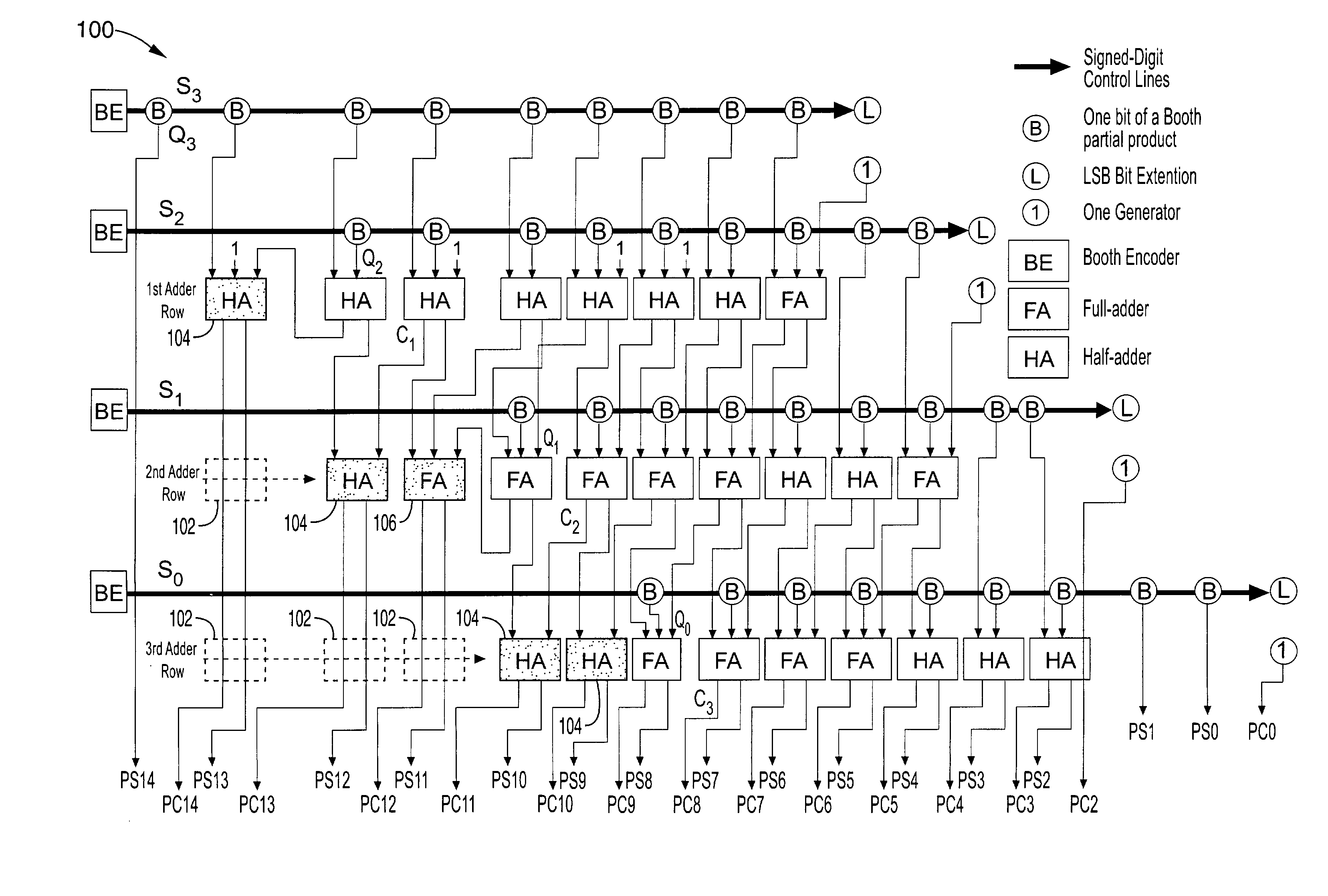
[0038]Accordingly, the present invention comprises a low-power array multiplier which is preferably Booth-encoded for many applications. Its architecture is suitable for DSP applications where one of the input signals has a large dynamic range. We take advantage of the encoding property of a Booth encoder and modify the standard adder array to reduce the total switching activity inside the array. As a result, power dissipation is reduced.

[0039]Although the description above contains many specificities, these should not be construed as limiting the scope of the invention but as merely providing illustrations of some of the presently preferred embodime...


PUM


Abstract

An enhanced Booth-encoded adder-array multiplier where the low transition probability partial-products are generated and the adder array has been reorganized to reduce power dissipation when the Booth-encoded input has a large dynamic range. The architecture does not require extra circuits or routing overhead. Power dissipation is reduced by ordering the sequence of partial-product additions such that an increasing sequence of “transition probabilities” is encountered.

Description

CROSS-REFERENCE TO RELATED APPLICATIONS[0001]This application claims priority from U.S. provisional application Ser. No. 60 / 328,365 filed on Oct. 9, 2001, incorporated herein by reference.STATEMENT REGARDING FEDERALLY SPONSORED RESEARCH OR DEVELOPMENT[0002]This invention was made with Government support under Grant No. MIP-9632698, awarded by the National Science Foundation. The Government has certain rights in this invention.REFERENCE TO A COMPUTER PROGRAM APPENDIX[0003]Not ApplicableBACKGROUND OF THE INVENTION[0004]1. Field of the Invention[0005]The present invention pertains generally to array multipliers, and more particularly to a Booth-encoded array multiplier architecture wherein low transition probability partial-products are generated, and the adder array is re-arranged according to the partial-products' signal transition probabilities.[0006]2. Description of the Background Art[0007]Multiplication is a ubiquitous operation in digital signal processing (DSP) applications. Th...

Claims


Application Information

Patent Timeline
Patent Type & Authority Patents(United States)
IPC IPC(8): G06F7/52G06F7/533
CPCG06F7/5338
Inventor WILLSON, JR., ALAN N.YU, ZHANWASSERMAN, LARRY S.
Owner RGT UNIV OF CALIFORNIA
Why Eureka
Try Eureka