Internal combustion engine comprising a connecting means for connecting a first section of a wire harness on a cylinder head housing to a second section of the same

a technology of internal combustion engine and connecting means, which is applied in the direction of fuel injection apparatus, basic electric elements, electric devices, etc., can solve the problems of high manufacturing cost of parts themselves, vibration and mechanical stress on wire harnesses, and achieve uniform clamping force, low cost, and easy installation

Active Publication Date: 2007-06-05
MOTOREN UND TURBINEN UNION MUNCHEN GMBH
View PDF15 Cites 7 Cited by
  • Summary
  • Abstract
  • Description
  • Claims
  • Application Information

AI Technical Summary

Benefits of technology

[0007]The invention is based on the task of providing a connecting means for the interface between the wire harness and the cylinder head housing which is low in cost, easy to install, and leakproof.
[0008]According to the invention, the connecting means comprises a terminal carrier and a boot and both the terminal carrier and the boot have means by which they lock themselves in position. In the case of the boot, the self-locking means is realized in the form of a latching ring or a latching lobe. In the case of the terminal carrier, the self-locking means is realized in the form of latching lobes. In the installed state, the terminal carrier is fixed in place on the cylinder head housing by the latching lobes, which grip under the cylinder head housing, which has the effect of sealing off the interior space. Then the boot is fixed in place on the terminal carrier by means of the latching ring or latching lobe. No additional work steps are required to attach the boot to the terminal carrier. Nor is there any need for fastening means such as screws or bores. The latching ring in the boot offers the advantage that the boot, to which a corrugated hose is attached, can be rotated to any angle on the terminal carrier. The connecting means is designed to last for the predicted life of a large diesel engine; that is, the connecting means is designed to withstand the effects of vibration for this period of time.
[0009]In one embodiment, it is proposed that the terminal carrier be provided with terminals and covers, each terminal consisting of a compression spring and a conductor strip. The second section of the wire harness is permanently connected to the conductor strip by a process such as soldering or crimping. In addition, the second section of the wire harness is embedded in the material of the terminal carrier. This guarantees both leak-tightness and the ability to withstand vibrations. Each of the individual wires of the first section of the wire harness is held in place between the compression spring and the conductor strip by the elastic force of the compression spring. The advantage of this arrangement is that the counterplug at the end of the first section of the wire harness can be eliminated. The only tool required to attach the first section of the wire harness to the terminal carrier is a screwdriver. In addition, the clamping action of the compression spring guarantees a uniform clamping force even under vibrational loads and thus also a uniform transition resistance between the wires of the first section of the wire harness and the conductor strip. In comparison with a conventional screw terminal connection, there is no need to retighten the screw. It is known that, in a screw connection of this type, the copper will creep and the screw will loosen.
[0010]Because the inventive connecting device does not need to be screwed in place, sealed, or aligned, the assembly time required is cut in half by comparison with the plug-bushing concept.

Problems solved by technology

The engine vibrations also subject the wire harness to mechanical stress at the pass-through point.
The problem here is that the wire harness can suffer mechanical damage as a result of excessive tightening torque when the boot is attached to the cylinder head.
The problem with this plug-bushing concept is that the manufacturing of the parts themselves is expensive and the fabrication of the first section of the wire harness with the counterplug is complicated.
Another difficulty is that the service life of a plug-bushing concept (3,000 hours of operation) is much shorter than the service life of a large diesel engine (more than 20,000 hours of operation).
The plug-bushing concept therefore cannot be used in large diesel engines.

Method used


Image

  • Internal combustion engine comprising a connecting means for connecting a first section of a wire harness on a cylinder head housing to a second section of the same
  • Internal combustion engine comprising a connecting means for connecting a first section of a wire harness on a cylinder head housing to a second section of the same
  • Internal combustion engine comprising a connecting means for connecting a first section of a wire harness on a cylinder head housing to a second section of the same

Examples


Embodiment Construction

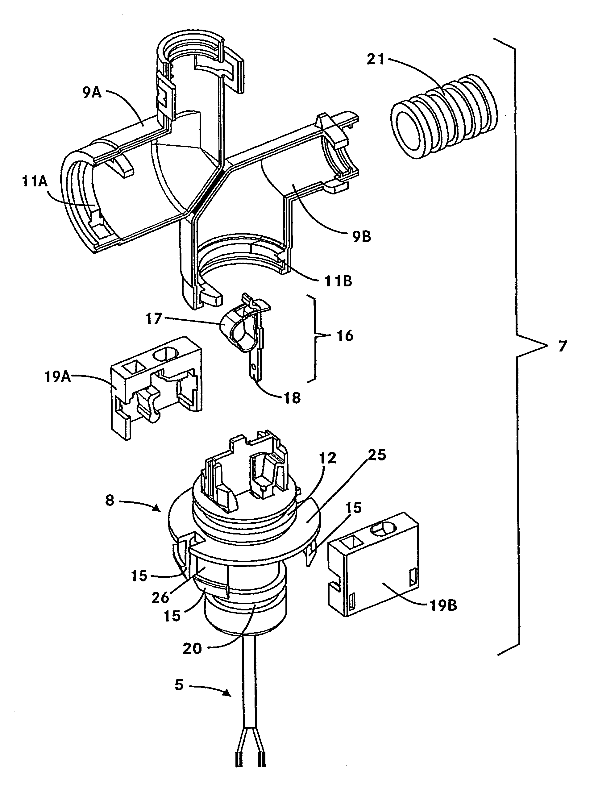
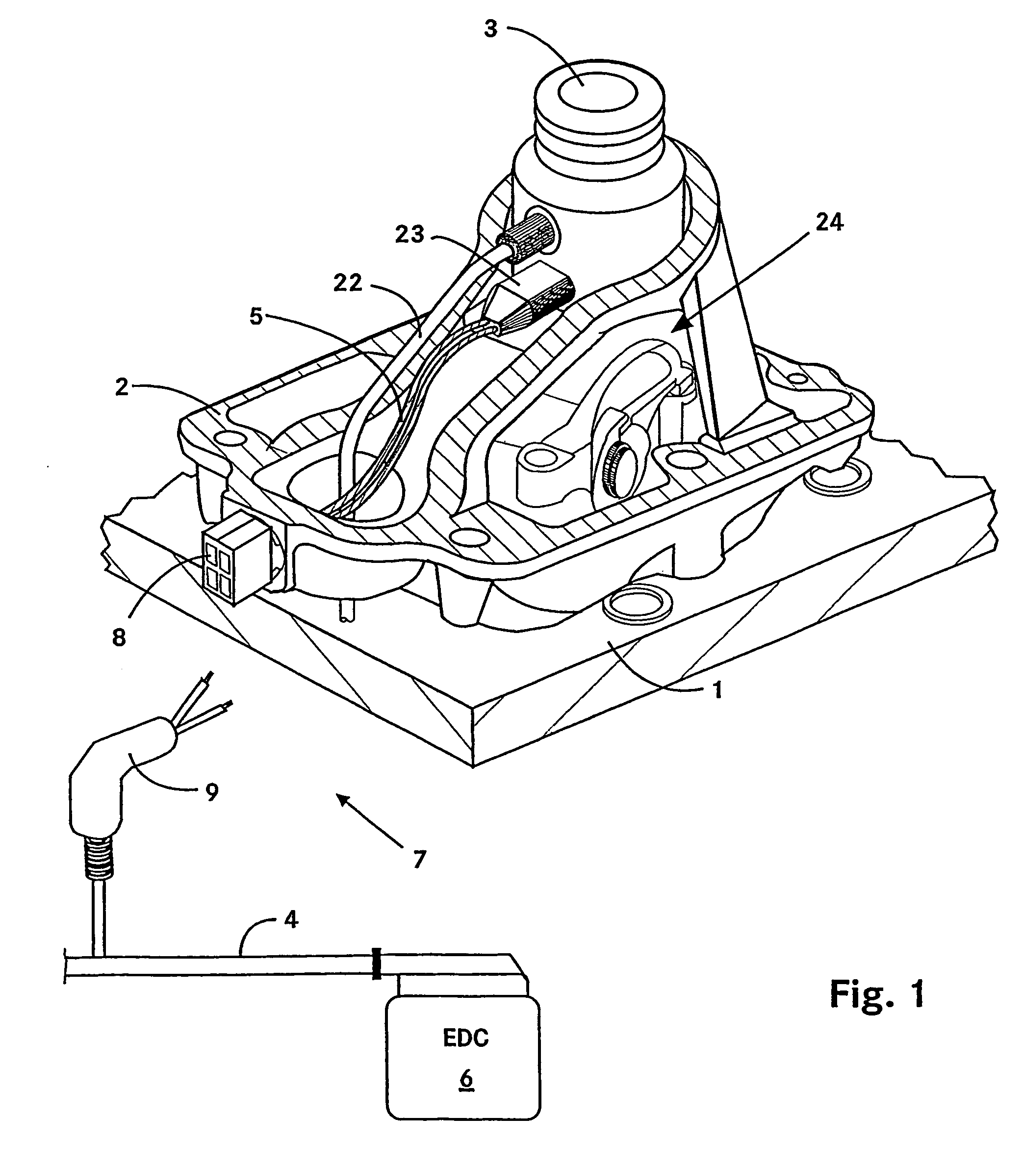
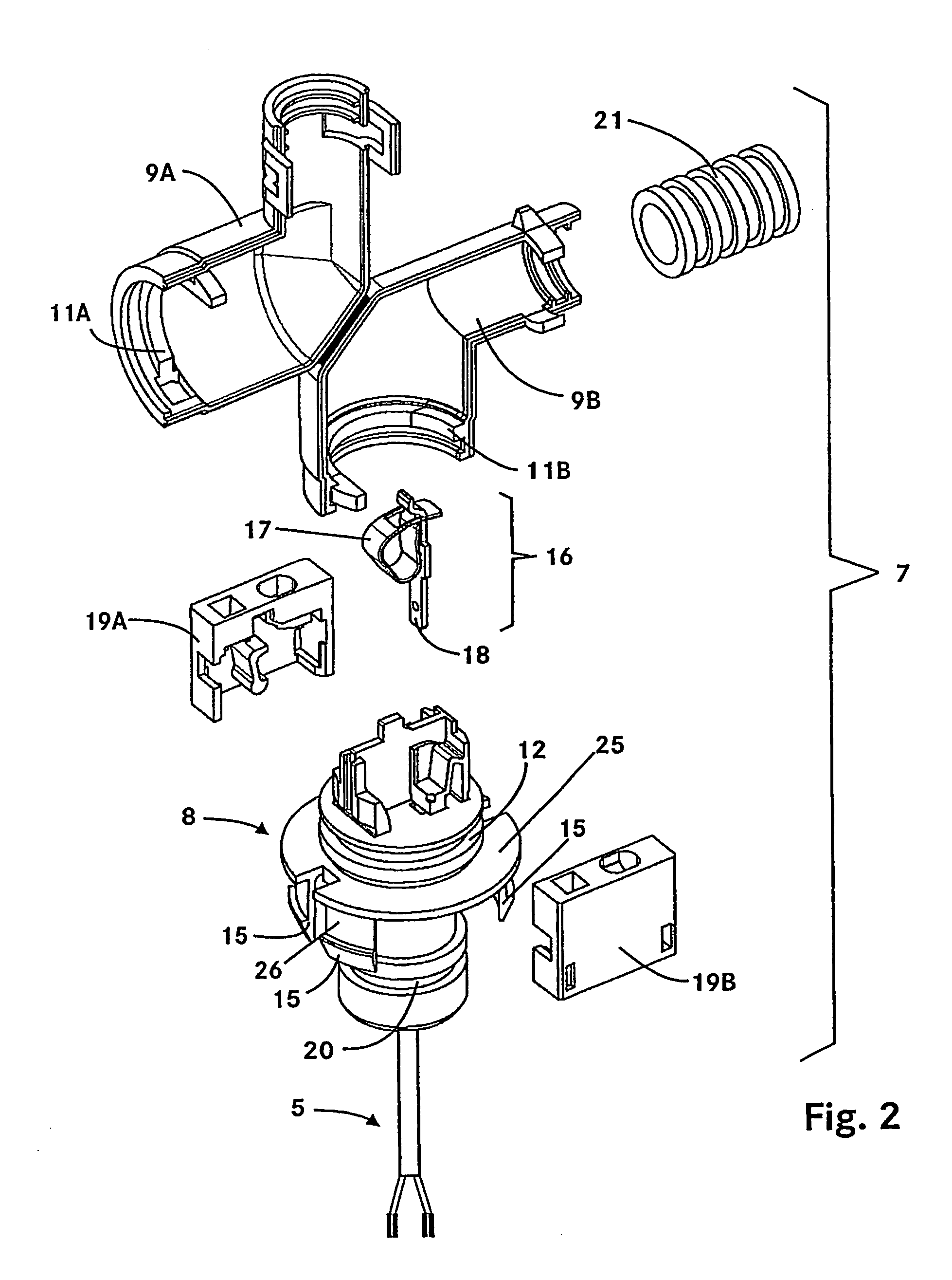
[0018]FIG. 1 shows the lower half of a cylinder head housing 2 on a crankcase housing 1 of an internal combustion engine. In the cylinder head housing 2 are an injector 3 and a valve driver 24. Through a high-pressure line 22, fuel is supplied under pressure to the injector 3 from, for example, a high-pressure reservoir of a common-rail system. The switching state of the injector 3 is determined by an electronic controller 6 (EDC). The signals are transmitted over a wire harness. This consists of a first section 4 and a second section 5. The first section 4 of the wire harness extends from the electronic controller 6 to the connecting means 7. The connecting means 7 represents the interface between the wire harness and the cylinder head housing. The second section 5 of the wire harness extends through the interior of the cylinder head housing 2 from the connecting means 7 to the injector 3. The end of the second section 5 facing away from the connecting means 7 is connected to the i...


PUM


Abstract

The invention relates to an internal combustion engine comprising an injector (3) which is arranged in the cylinder head. According to the invention, said internal combustion engine is provided with a connecting means (7) for connecting a first section (4) of the wire harness to a second section (5) of the same. Said connecting means (7) comprises a terminal carrier (8) and a cover (9, 10). Both the terminal carrier (8) and the cover (9, 10) are provided with self-locking means. In this way, a cost-effective connecting means (7) is provided, which can be easily and quickly mounted.

Description

PRIORITY CLAIM[0001]This is a 35 U.S.C. §371 National Stage of International Application No. PCT / EP2003 / 008674, filed on Aug. 6, 2003. Priority is claimed on that application and on the following application:[0002]Country: Germany, Application No. 102 36 505.9, Filed: Aug. 9, 2002.BACKGROUND OF THE INVENTION[0003]The invention pertains to an internal combustion engine with a connecting means for connecting a first section to a second section of a wire harness on a cylinder head housing. The invention further relates to a process for installing such a harness.[0004]In an internal combustion engine, the fuel is injected into the combustion chamber through an injector. An electronic controller transmits the appropriate actuating signals, which determine the switching state of the injector. The signals are transmitted over a wire harness. Because the injector is located inside the cylinder head housing, the wire harness must pass through the cylinder head housing. This pass-through is c...

Claims


Application Information

Patent Timeline
Patent Type & Authority Patents(United States)
IPC IPC(8): H01T13/00H01T13/08F02F1/24F02M51/00
CPCF02F1/24F02M51/005
Inventor BARRENA, OSCAR BLASCOHANNING, WALTERLUTZE, DIETMAR
Owner MOTOREN UND TURBINEN UNION MUNCHEN GMBH
Why Eureka
Try Eureka