
Flexible hose for a vacuum cleaner and fabricating method thereof

Inactive Publication Date: 2007-06-05
JI WOONG KIM
View PDF4 Cites 5 Cited by
  • Summary
  • Abstract
  • Description
  • Claims
  • Application Information

AI Technical Summary

Benefits of technology

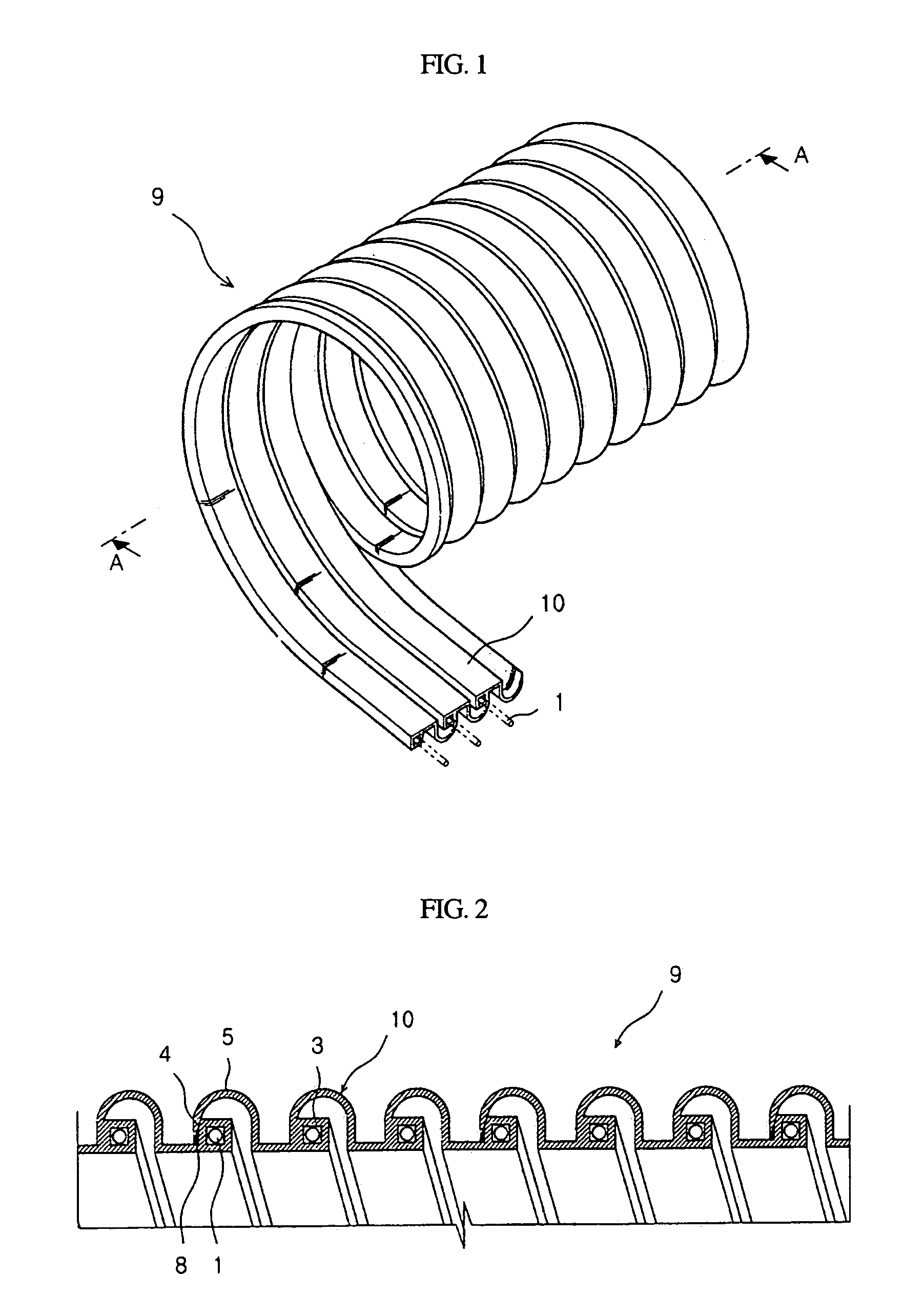
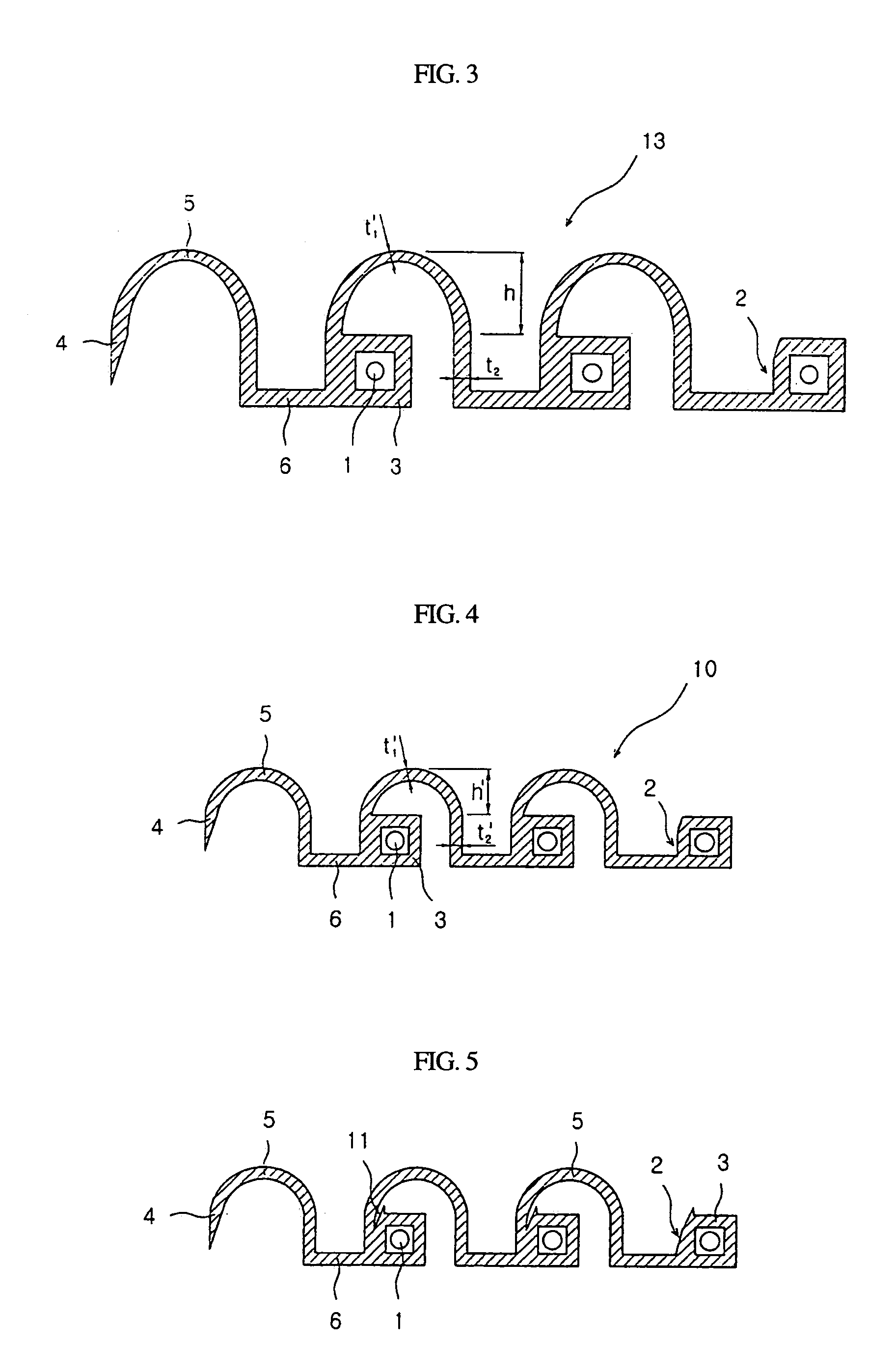
[0010]An object of the present invention is to provide a flexible hose for a vacuum cleaner and a fabricating method thereof. The flexible hose having a good cross-section as if molded with one extrusion molding band although the extrusion molding band is elongated in a sizing mold by extruding the primary extrusion molding band drawn from the extruder whose cross-section is different from that of the related art, so as to prevent the cross-section of the multi-extrusion molding band from being deformed and the semicircular portion from being adhered to an upper portion of the electric wire embedding portion when a plurality of extrusion molding bands are pre-molded into one primary extrusion molding band and the primary extrusion molding band is fixed dimensionally in a sizing mold to draw a final multi-extrusion molding band.

Problems solved by technology

When using four electric wires, a danger of a short circuit may occur because two electric wires are inserted into any one of the three lines of extrusion molding bands.
For conventional flexible hoses, the design is complicated in the coupling structure of the extrusion molding bands, so that the working efficiency is lowered.
Since the flexible hose is bonded at many points by bond or resin, it is problematic in reliably fix the extrusion molding bands, therefore for the conventional flexible hoses the product reliability is low.
Since there exist many bonding points, the pitch of the conventional flexible hose is not uniform and the failure ratio is high.
In addition, since the bonding portion has joint surfaces on both sides, the flexibility of the flexible hose is lowered and its thickness is large so that too much source material is consumed.

Method used


Image

  • Flexible hose for a vacuum cleaner and fabricating method thereof
  • Flexible hose for a vacuum cleaner and fabricating method thereof
  • Flexible hose for a vacuum cleaner and fabricating method thereof

Examples


Embodiment Construction

[0029]Reference will now be made in detail to the preferred embodiments of the present invention, examples of which are illustrated in the accompanying drawings. Wherever possible, the same reference numbers will be used throughout the drawings to refer to the same or like parts.

[0030]Referring to FIGS. 8 and 9, in the related art, a flexible hose 9 for a vacuum cleaner includes two or three long extrusion molding bands 7 which are attached to each other and wound cylindrically at a predetermined angle. Each of the extrusion molding bands 7 has a cross-section configured to include a rectangular electric embedding portion 3 having an embedded electric wire 1 and a bonding portion 2, a semicircular portion 5 having a bonding end at an end thereof, and a connecter connecting the electric embedding portion 3 and the semicircular portion 5. Bonding ends 4 and bonding portions 2 of the two or three long extrusion molding bands 7 are bonded by an adhesive 8, and the bonding end 4 of the e...


PUM

PropertyMeasurementUnit
Thicknessaaaaaaaaaa
Flexibilityaaaaaaaaaa

Abstract

Disclosed is a flexible hose for a vacuum cleaner and a fabricating method thereof. The fabrication method includes the steps of: extruding a primary extrusion molding band 13 having a larger size than a size of a finished state while embedding an electric wire 1 in the primary extrusion molding band 13 at a first extruder 12; molding a multi-extrusion molding band 10 in the size of the finished state at a sizing mold 14; and winding the multi-extrusion molding band 10 at a predetermined angle at a bonder and bonding a bonding portion 2 of the electric embedding portion 3 with a bonding end 4 of the semicircular portions 5 positioned on both sides of the multi-extrusion molding band 10 by using adhesive 8.

Description

BACKGROUND OF THE INVENTION[0001]1. Field of the Invention[0002]The present invention relates to a flexible hose for a vacuum cleaner, in which a long extrusion molding band is wound in a cylindrical form, and a fabricating method thereof, and more particularly, to a flexible hose for a vacuum cleaner, in which a multi-band extrusion molding is employed such that a plurality of extrusion molding bands are arranged in parallel and connected to one another, wound in a cylindrical form, and a fabricating method thereof is also included.[0003]2. Description of the Prior Art[0004]A flexible hose for a vacuum cleaner is made cylindrically by winding an extrusion molding band, which is extrusion-molded in a single line. The cross-section of the extrusion molding band may include a wave shape ‘’. One side of the cross-section may include an electric wire embedding portion and the other side may include a semicircle portion having a semicircle shape. When the extrusion molding band is wound ...

Claims


Application Information

Patent Timeline
IPC IPC(8): B65H81/00A47L9/24B32B1/08F16L11/118F16L11/16
CPCA47L9/24F16L11/1185B29C53/785F16L11/16Y10T428/139
Inventor PARK, IL-SOOK
Owner JI WOONG KIM
Learn More