Customizable background for video communications

a video communication and background technology, applied in the field of image acquisition system, can solve the problems of completely muting image information, distracting background of receiving participants, and offending or otherwise upset the other party, and achieve the effect of substantial bandwidth savings

Active Publication Date: 2007-06-05
AVAYA INC
View PDF16 Cites 166 Cited by
  • Summary
  • Abstract
  • Description
  • Claims
  • Application Information

AI Technical Summary

Benefits of technology

[0018]In one configuration, the background image information may be omitted from the transmitted image information and the substitute image information added by the receiver or second participant's communication device. For example, the receiving party's communication device can receive just the first participant's image and overlay it on a desired background, such as a selected color. In one configuration, the background is transmitted once with the initial image information (which includes the desired and substitute image information) and thereafter only the desired image information from the currently acquired image information is provided to the second participant's communication device by the first participant's video telecommunications system. The second participant's communication device combines the substitute image information with the desired image information as it is received. This can effect a substantial bandwidth savings.

Problems solved by technology

While muting does provide a degree of privacy, it can be overkill.
Moreover, completely muting the image information may offend or otherwise upset the other party.
For example, the receiving participant may find the other party's background distracting.
While this approach is attractive in certain applications, it fails to provide the receiver with freedom to alter the background as he or she wishes.

Method used


Image

  • Customizable background for video communications
  • Customizable background for video communications
  • Customizable background for video communications

Examples


Embodiment Construction

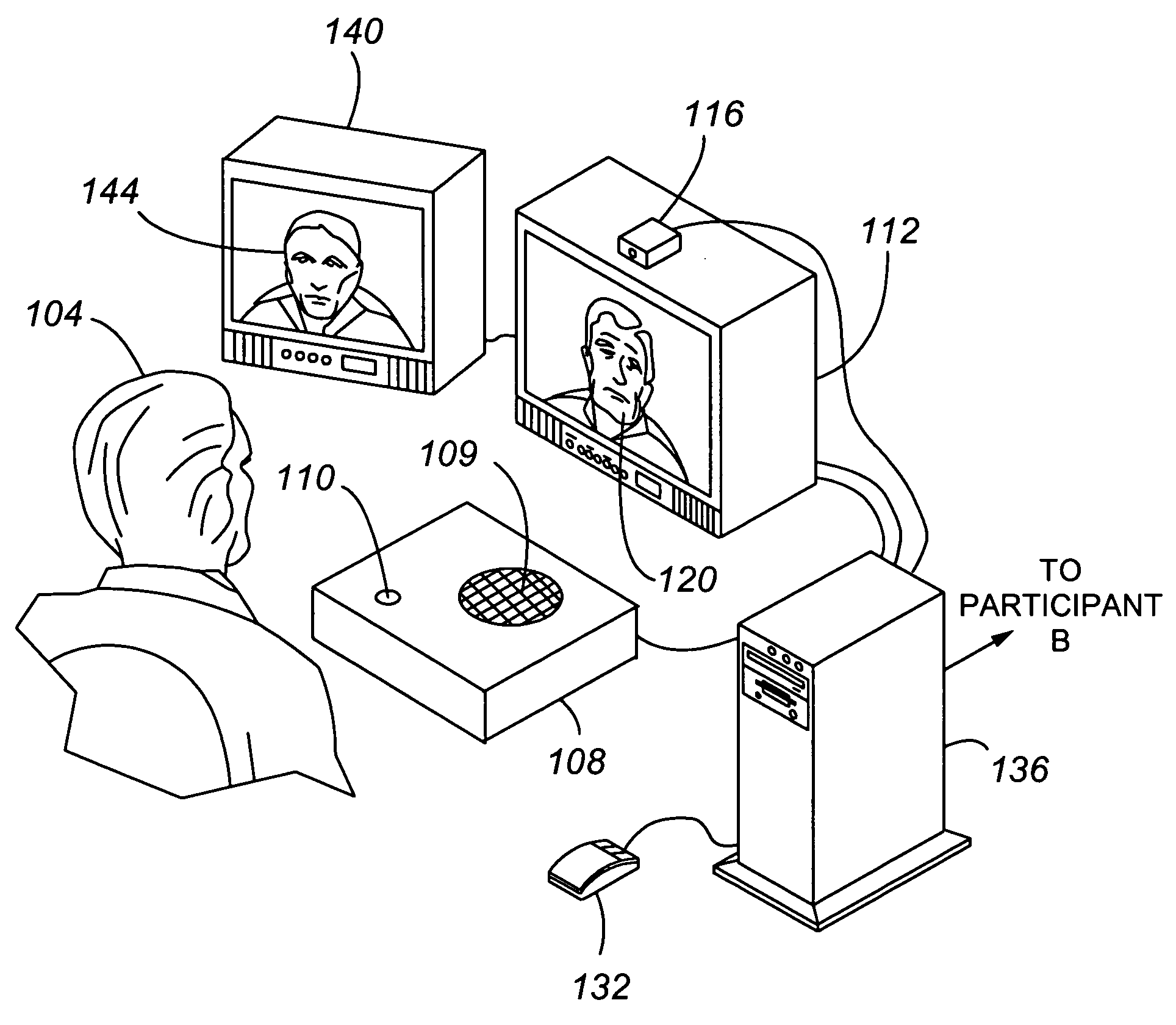
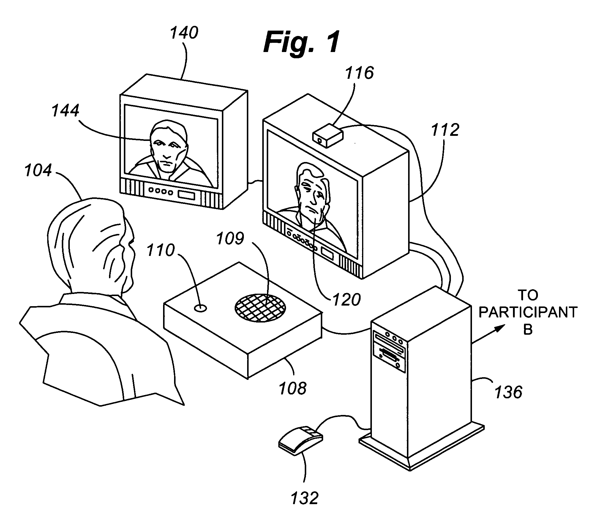
[0029]With reference to FIG. 1, components of a video telecommunications system 100 in accordance with an embodiment of the present invention are illustrated. In general, the video telecommunications system 100 comprises a first participant 104, an audio transceiver 108, which includes a speaker 109 and a microphone 110, first and second video displays 112 and 140, and a camera 116. The video telecommunications system 100 allows the first participant 104 to communicate both audibly and visibly with a second participant at a remote location. In FIG. 1, an image 120 of the second participant is shown in the display 112 and the image 144 of the first participant 104 is shown in the display 140.

[0030]The camera 116 acquires the image information of the first participant 104. In one configuration, the camera is connected to a Universal Serial Bus (USB) of the Personal Computer or PC136 running the Microsoft Windows 2000™ operating system. Standard Windows Driver Model methods are used to...


PUM


Abstract

A video telecommunications system 100 for effecting a communication between at least first and second participants including
    • an image alteration agent 358 that (i) removes desired and/or undesired image information 370 and 374 from the acquired image information 362 to form filtered image information 378 and the removed information and (ii) combines the filtered image information 378 and/or the image information 370 and 374 with substitute image information 382 to form composite image information 366; and
    • a video communication infrastructure 304 that transmits the composite image information 366 to a communication device associated with the second participant 120. The composite image information 366 excludes undesired image information 374.

Description

CROSS REFERENCE TO RELATED APPLICATION[0001]Cross reference is made to U.S. patent application Ser. No. 10 / 949,781, filed Sep. 24, 2004, entitled “CAMERA FRAME DISPLAY”, which is incorporated herein by this reference.FIELD OF THE INVENTION[0002]The invention relates generally to an image acquisition system and particularly to an image acquisition that is user customizable to provide a selected video display to another participant to a video telecommunication.BACKGROUND OF THE INVENTION[0003]The use of video telephony, which allows remote parties to both see and hear one another, is becoming increasingly popular. As used herein, “video telephony” refers to visual communication using both video and audio transmitted over a communications network. It includes both mobile and stationary video telephony. Typically, video telephony refers to packet-switched and circuit-switched, wireless and wired, audio and video communications, such as Voice Over IP or VOIP communications, and video tel...

Claims


Application Information

Patent Timeline
Patent Type & Authority Patents(United States)
IPC IPC(8): H04N7/14
CPCH04N7/147
Inventor BECK, ALEXANDER JOHN GRAYBLAIR, COLINLANG, ANDREW W.MCNAMARA, PAUL THOMASTHAMBIRATNAM, DAVID PRESHANWAN, JAMES K.
Owner AVAYA INC
Why Eureka
Try Eureka