Method and system for CT imaging using a distributed X-ray source and interpolation based reconstruction

a distributed x-ray source and reconstruction technology, applied in tomography, instruments, applications, etc., can solve the problems of various motion-related image artifacts, blurring, streaking, and discontinuities of ct imaging techniques,

Active Publication Date: 2007-06-05
GENERAL ELECTRIC CO
View PDF23 Cites 23 Cited by
  • Summary
  • Abstract
  • Description
  • Claims
  • Application Information

AI Technical Summary

Problems solved by technology

CT imaging techniques, however, may present certain challenges when imaging dynamic internal tissues, such as the heart.
For example, in cardiac imaging, the motion of the heart causes inconsistencies in the projection data, which, after reconstruction, may result in various motion-related image artifacts such as blurring, streaking, or discontinuities.
While such fifth generation systems could be made to scan faster, they suffer from a non co-planar detector and source configuration.
As a result, such systems tend to collect incomplete data, and suffer from image artifacts as a result.
However, as the rotational speed of the gantry increases, the centripetal force required for gantry components also increases.
The increasing centripetal force and the tolerances of the gantry components may comprise, therefore, a mechanical limitation to increases in gantry angular velocity.
Both mechanical and X-ray flux considerations, therefore, are obstacles to increasing the gantry rotation speed sufficiently to achieve a temporal resolution of 20 ms or better in CT reconstructions.
However, existing systems typically acquire projection data for a limited extent of the patient or object being scanned.
Larger detectors, however, may be undesirable for a variety of reasons.
For instance, as one might expect, larger detectors and associated acquisition electronics are both more costly and more difficult to produce.
In addition, the mechanical subsystem responsible for supporting and / or rotating a larger detector may also need to be larger and more complex and / or may be subject to greater mechanical stress.
The increased cone angle between the source and detector periphery is in turn associated with increased cone-beam artifacts in the reconstructed images depending on the choice of data acquisition protocol and reconstruction algorithm.
When the cone angle increases beyond a certain limit, the degradation of the image quality may become severe for axial, or step-and-shoot scanning.
For the foregoing reasons, increasing the scan coverage by simply increasing the detector coverage, i.e., size of the detector, is not a sufficient or complete solution.

Method used


Image

  • Method and system for CT imaging using a distributed X-ray source and interpolation based reconstruction
  • Method and system for CT imaging using a distributed X-ray source and interpolation based reconstruction
  • Method and system for CT imaging using a distributed X-ray source and interpolation based reconstruction

Examples


Embodiment Construction

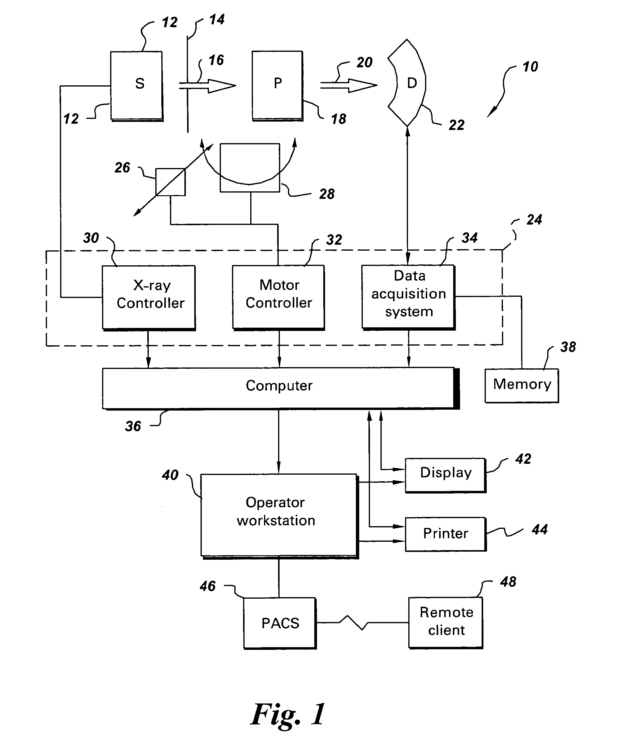
[0020]FIG. 1 illustrates diagrammatically an imaging system 10 for acquiring and processing image data, in accordance with one aspect of the present technique. In the illustrated embodiment, system 10 is a computed tomography (CT) system designed to acquire X-ray projection data, to reconstruct the projection data into an image and to process the image data for display and analysis in accordance with the present technique. Though the imaging system 10 is discussed in the context of medical imaging, the techniques and configurations discussed herein are applicable in other non-invasive CT imaging contexts, such as baggage or package screening.

[0021]In the embodiment illustrated in FIG. 1, the CT imaging system 10 includes a distributed source 12 of X-ray radiation positioned adjacent to a collimator 14. As described herein, the CT imaging system 10 may be configured in a variety of ways to improve spatial and temporal resolution, to improve image quality, and / or to improve longitudin...


PUM

PropertyMeasurementUnit
rotation timeaaaaaaaaaa
fan angleaaaaaaaaaa

Abstract

A method for Computed Tomography (CT) imaging is provided. The method comprises rotating a gantry at a substantially slow rotation speed about a volume of interest. The gantry comprises a combination of X-ray source points. The X-ray source points comprise one or more discrete emission points and an arc of discrete or continuous X-ray source points. The method then comprises obtaining projection data from the combination of X-ray source points and performing a suitable reconstruction based on the projection data obtained from the combination of X-ray source points, to generate one or more reconstructed images.

Description

BACKGROUND[0001]The invention relates generally to the field of CT imaging and more specifically to a distributed source configuration for the imaging of dynamic internal tissues. In particular, the invention relates to an interpolation-based reconstruction technique for performing full field of view imaging of dynamic internal tissues, using the source configurations.[0002]Computed tomography (CT) imaging systems measure the attenuation of X-ray beams passed through a patient from numerous angular positions about the patient. Based upon these measurements, a computer is able to reconstruct images of the linear attenuation coefficient of the portions of a patient's body responsible for the radiation attenuation. As will be appreciated by those skilled in the art, these images are based upon separate examination of a series of angularly displaced images of the transmitted X-ray beam intensity. A CT system processes X-ray intensity data to generate two-dimensional (2D) maps of the lin...

Claims


Application Information

Patent Timeline
Patent Type & Authority Patents(United States)
IPC IPC(8): A61B6/00G01N23/00H05G1/70
CPCA61B6/032A61B6/4028A61B6/4085H05G1/52
Inventor EDIC, PETER MICHAELBASU, SAMIT KUMARDE MAN, BRUNO KRISTIAAN BERNARD
Owner GENERAL ELECTRIC CO
Why Eureka
Try Eureka