Linear damper

a damper and linear technology, applied in the direction of friction dampers, solid based dampers, springs/dampers, etc., can solve the problems of inability to use oil dampers, virtually impossible to eliminate oil leakage in reality, and inability to completely eliminate oil leakage, etc., to avoid damper effect degradation, reduce costs, and high response

Inactive Publication Date: 2007-06-12
TOK BEARING CO LTD
View PDF11 Cites 10 Cited by
  • Summary
  • Abstract
  • Description
  • Claims
  • Application Information

AI Technical Summary

Benefits of technology

[0025]It is accordingly an object of the present invention to provide a linear damper capable of compensating for the drawbacks of oil dampers and air dampers while directly and effectively adopting the good points of the oil and air dampers, more particularly, a linear damper capable of offering the expected damping force without the use of oil or gas.
[0041]According to the first to tenth features, it is possible to exert a damping effect by use of the damping portion and the damping groove. Thus, the linear damper is operated without viscous fluid used in conventional oil dampers. Hence, the linear damper is capable of being used in a place where use of oil is undesirable, for example, in a place where food is handled. This makes it possible to extend the boundaries of environmental condition for use of dampers. There is no need of oil or air, and naturally no leak of oil or air. Hence a seal member for preventing the oil or air leakage is unnecessary, leading to cost reduction. Further, because of no use of the sealing member, it is possible to avoid damper effect degradation caused by an adverse effect of the tightening force of the seal.
[0042]Because a damping force is produced by pressing the damping portion against the damping groove, it is possible to provide a damper of further high response as compared with the case of using a gas of high compression, such as an air damper.
[0043]According to the fifth embodiment, the release mechanism is provided for removing a fore pressing the damping portion in the direction tapering the inner width of the damping groove. The spring for exerting the spring force in the direction removing the pressing force is provided in the first moving member. As a result, it is possible to quickly return the first moving member to the normal position.

Problems solved by technology

But however tight the seal is applied, the oil adhering to the rod or the like will inevitably leak to the outside.
A complete elimination of oil leakage is virtually impossible in reality.
Such characteristics of the oil damper produce the problem of the impossibility of using the oil damper in a situation where the adhesion of the oil to food or the like must be absolutely avoided.
In this respect, however, the problem is that the higher the precision of the seal structure, the higher the cost.
However, as the tightening force of the seal becomes increased, the friction increases.
This in turn causes impairment in the sliding performance of the rod and thus adversely affects the damping effect.
Further, a seal groove is required to hold the seal member, but the formation of the seal groove in itself requires time and effort.
This also becomes a factor in increasing the cost.
For the prevention of oil leakage and a reduction in slide resistance to a minimum, moreover, the surface of the rod 3 is required to be finished with a high degree of accuracy, naturally resulting in an increase in the cost.
In addition, another problem is that as compared with the machining techniques for resin and the like, metal work requires time and effort, so that the higher the degree of accuracy of machining metal is required, the higher the cost.
Whatever the case, the conventional oil dampers face the inescapable problems of not only a limited use but also a substantial increase in production costs.
However, if the gas leaks, it becomes next to impossible to expect a damping effect from the air damper.
In addition, to completely prevent the leakage of a gas composed of extremely small particles is much more difficult than to block the oil leakage.
As a result, though the air damper has no structural problems, the problem is that the air damper becomes functionally unusable due to the gas leakage.
Moreover, due to the high degree of compressibility of the gas or the like, the air damper has the characteristic of response inferior to that of the oil damper.
In other words, the oil damper is capable of having a long life to a certain extent, and promising to offer a strong damping force, but has the problem of the impossibility of being used in a situation where oil leakage is forbidden.
The air damper has no problems in respect to oil leakage, but has the problems of a short life and a somewhat inadequate response.

Method used


Image

  • Linear damper
  • Linear damper
  • Linear damper

Examples


first embodiment

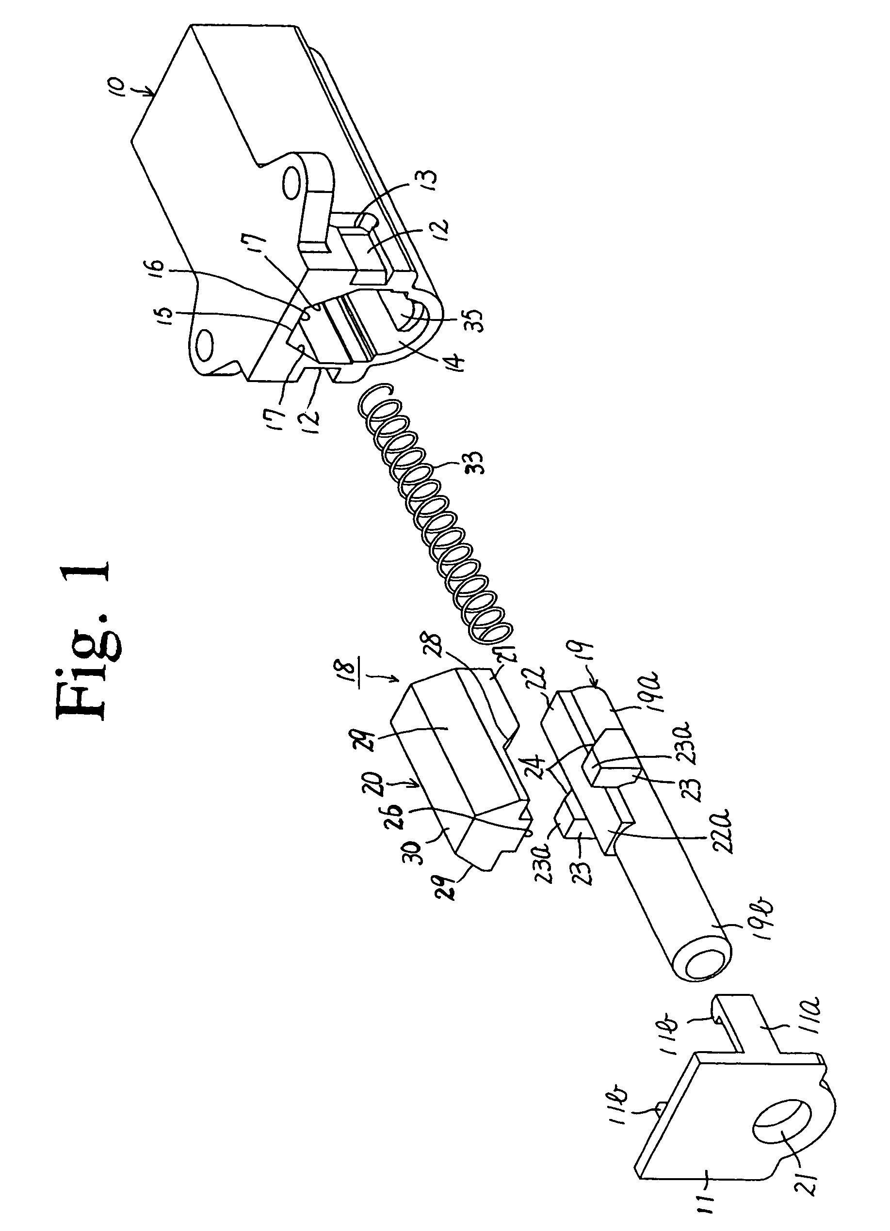
[0101]FIG. 1 to FIG. 6 illustrate a first embodiment according to the present invention.

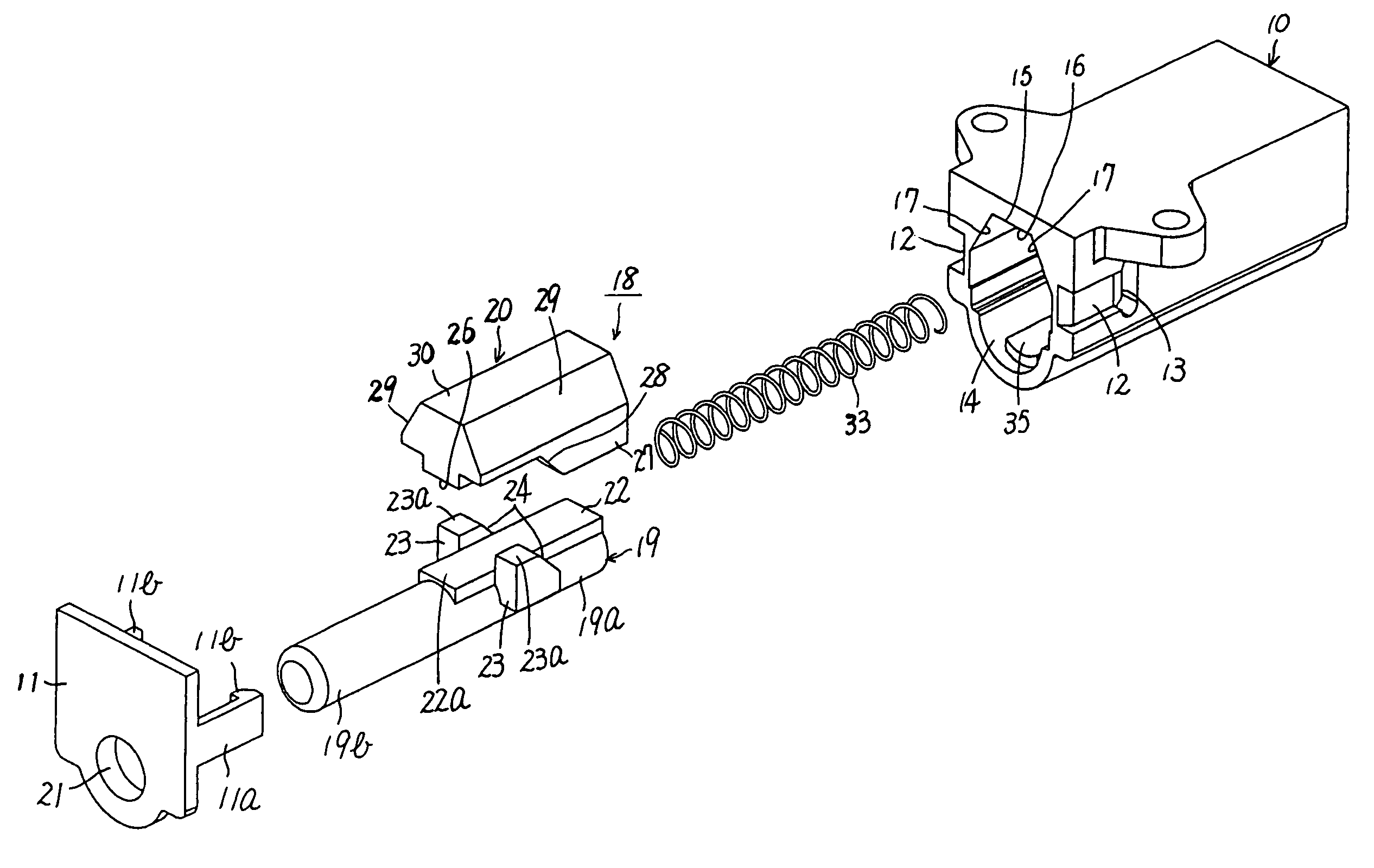
[0102]As shown in FIG. 1, a casing according to the present invention is constituted of a cylindrical-shaped casing body 10 and a cap 11. The casing body 10 has a closed end and an open end having an opening closed with the cap 11.

[0103]The cap 11 forming part of the casing has a pair of hooks 11a extending from the side faces of the cap 11. A pallet 11b is formed at the leading end of each hook 11a.

[0104]The casing body 10, correspondingly, has a pair of grooves 12 formed in both sides of the opening thereof. Each hook 11a snugly fits into the corresponding groove 12 when the cap 11 is fitted on the casing body 10. The groove 12 has an engaging recess 13 formed therein for receiving the pallet 11b when the hook 11a is snugly fitted into the groove 12. The pallets 11b of the hooks 11a are individually fitted into the engaging recesses 13 in this manner in order to prevent the cap 11 from disjoin...

third embodiment

[0148]FIG. 9 to FIG. 16 illustrate a third embodiment according to the present invention.

[0149]As shown in FIG. 9, a casing according to the present invention is constituted of a cylindrical-shaped casing body 10 and a cap 11. The casing body 10 has a closed end and an open end having an opening closed with the cap 11.

[0150]The cap 11 forming part of the casing has a pair of hooks 11a extending from the side faces of the cap 11. A pallet 11b is formed at the leading end of each hook 11a. Correspondingly, the casing body 10 has a pair of grooves 12 formed on both sides of the opening thereof. Each of the hooks 11a snugly fits into the corresponding groove 12 when the cap 11 is fitted on the casing body 10. The groove 12 has an engaging recess 13 formed therein for receiving the pallet 11b when the hook 11a is snugly fitted into the groove 12. The pallets 11b of the hooks 11a are respectively fitted into the engaging recesses 13 in this manner in order to prevent the cap 11 from disjo...

fifth embodiment

[0205]FIG. 19 to FIG. 23 illustrate a fifth embodiment according to the present invention.

[0206]As shown in FIG. 19, a casing according to the present invention is constituted of a cylindrical-shaped casing body 10 and a cap 11. The casing body 10 has a closed end and an open end having an opening closed with the cap 11.

[0207]As in the case of the first embodiment, the casing body 10 has a cylindrical portion 14 and a damping groove 15 formed inside in the axial direction. The cylindrical portion 14 and the damping groove 15 have the axes parallel to each other but the axis of the damping groove 15 is eccentric with respect to the cylindrical portion 14. The cylindrical portion 14 and the damping groove 15 are connected continuously to each other in the vertical direction.

[0208]The cylindrical portion 14 has an arc-shaped inner bottom portion formed opposite the damping groove 15 as shown in FIG. 20. The damping groove 15 has a flat ceiling face 16 opposing the cylindrical portion 1...


PUM


Abstract

Linear dampers are capable of offering an expected damping force without the use of oil or gas. A casing body 10 has a cylindrical portion 14 and a damping groove 15 continuing with each other and axially extending. The side face of the damping groove 15 are tapering faces 17 between which the space gradually opens up toward the opening of the damping groove 15. A slider 18 constituted of a first moving member 19 and a second moving member 20 is inserted into the casing 10. When the slider 18 is inserted into the casing 10, an inclined face 28 of the second moving member 20 and an inclined face 24 of the first moving member 19 are in contact with each other and tapering faces 29 of the second moving member 20 and the tapering faces 17 are in contact with each other.

Description

BACKGROUND OF THE INVENTION[0001]1. Field of the Invention[0002]This invention relates to a linear damper exerting an effective damping force without the use of fluid.[0003]2. Description of the Related Art[0004]FIG. 57 illustrates a conventionally known linear damper exerting a damping effect on movement in the axial direction.[0005]The conventional linear damper includes a cylindrical-shaped casing 1, a piston 2 sliding in contact with the inner surface of the casing 1, and a rod 3 connected to the piston 2. The casing 1 has an open end 1a and a closed end 1b. The open end 1a is covered with a cap 4 for enclosure.[0006]The piston 2 divides the inside of the enclosed casing 1 into two chambers 5a and 5b which contain viscous fluid.[0007]The casing 1 has a groove 6 formed on the inner peripheral surface thereof. The groove 6 formed serves as a passageway allowing the flow of the viscous fluid along the sliding surface between the casing 1 and the piston 2.[0008]The cap 4 has a rod h...

Claims


Application Information

Patent Timeline
Patent Type & Authority Patents(United States)
IPC IPC(8): F16F11/00F16F7/08F16F9/30
CPCF16F7/08
Inventor NAMIKI, SHINPEITAKAHASHI, KENJI
Owner TOK BEARING CO LTD
Why Eureka
Try Eureka