Fluid coolant union

Active Publication Date: 2007-06-12
DEUBLIN
View PDF22 Cites 15 Cited by
  • Summary
  • Abstract
  • Description
  • Claims
  • Application Information

AI Technical Summary

Benefits of technology

[0006]The present invention provides a novel fluid coolant union which utilizes chamfered seal faces on at least one of the non-rotating and rotating portion floating seal assembly facings of the coolant union. Such coolant unions permit the handling of multiple cooling media, such as water-based, oil-based, air-oil mist based and air-based coolants to be directed through the coolant union. Additionally, it has been determined that by chamfering the seal faces in accordance with the present invention, the handling of the multiple media with a single seal balance is permitted while controlling leakage for the water-based, the oil-based, the air-oil mist and the air-based media to minimum levels. The chamfered seal face of at least one of the floating seal asse

Problems solved by technology

During this dry-running condition, the increased wear on the seal facings results in leakage about the seal facings which ultimately require replacement of one or both of the seal members.
Such replacement of the seal facing and the rotor assembly are expensive and tim

Method used


Image

  • Fluid coolant union
  • Fluid coolant union
  • Fluid coolant union

Examples


Example

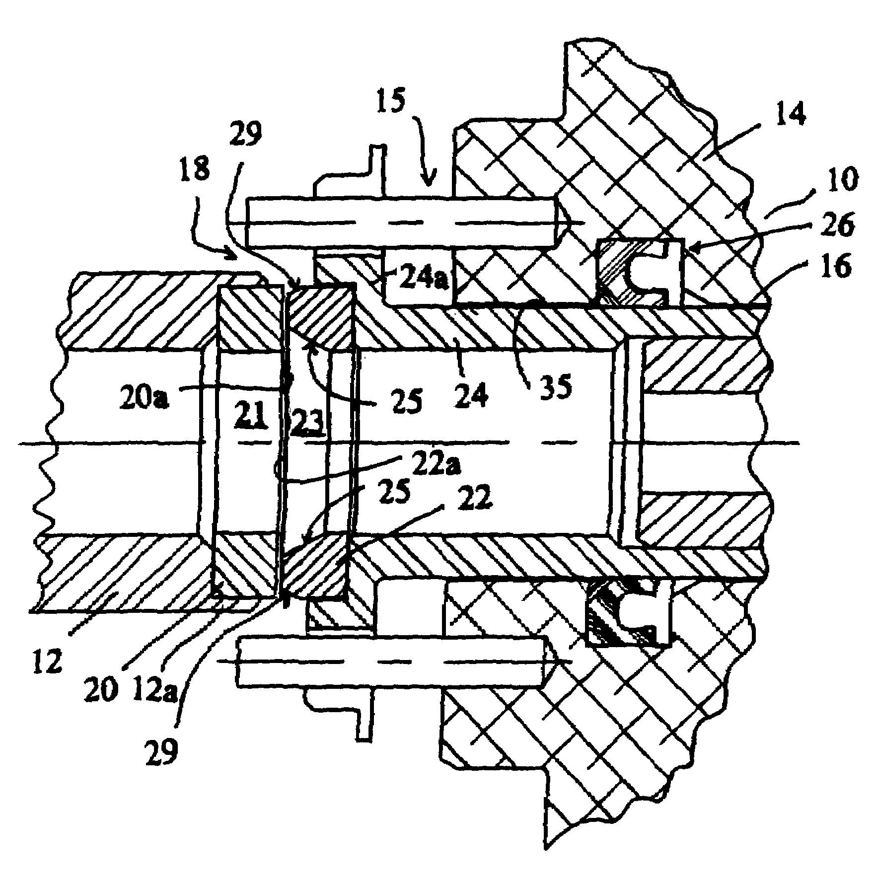
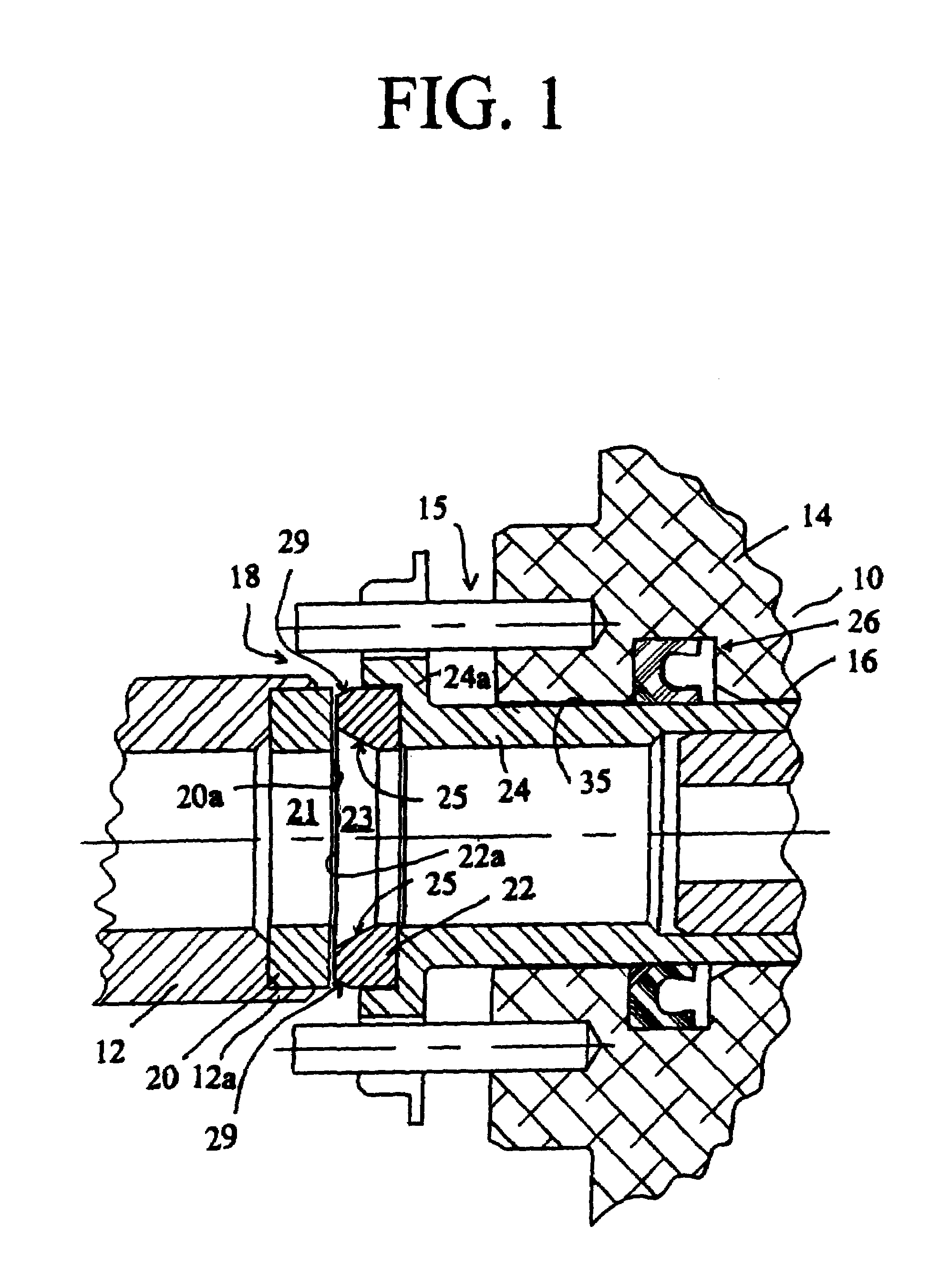
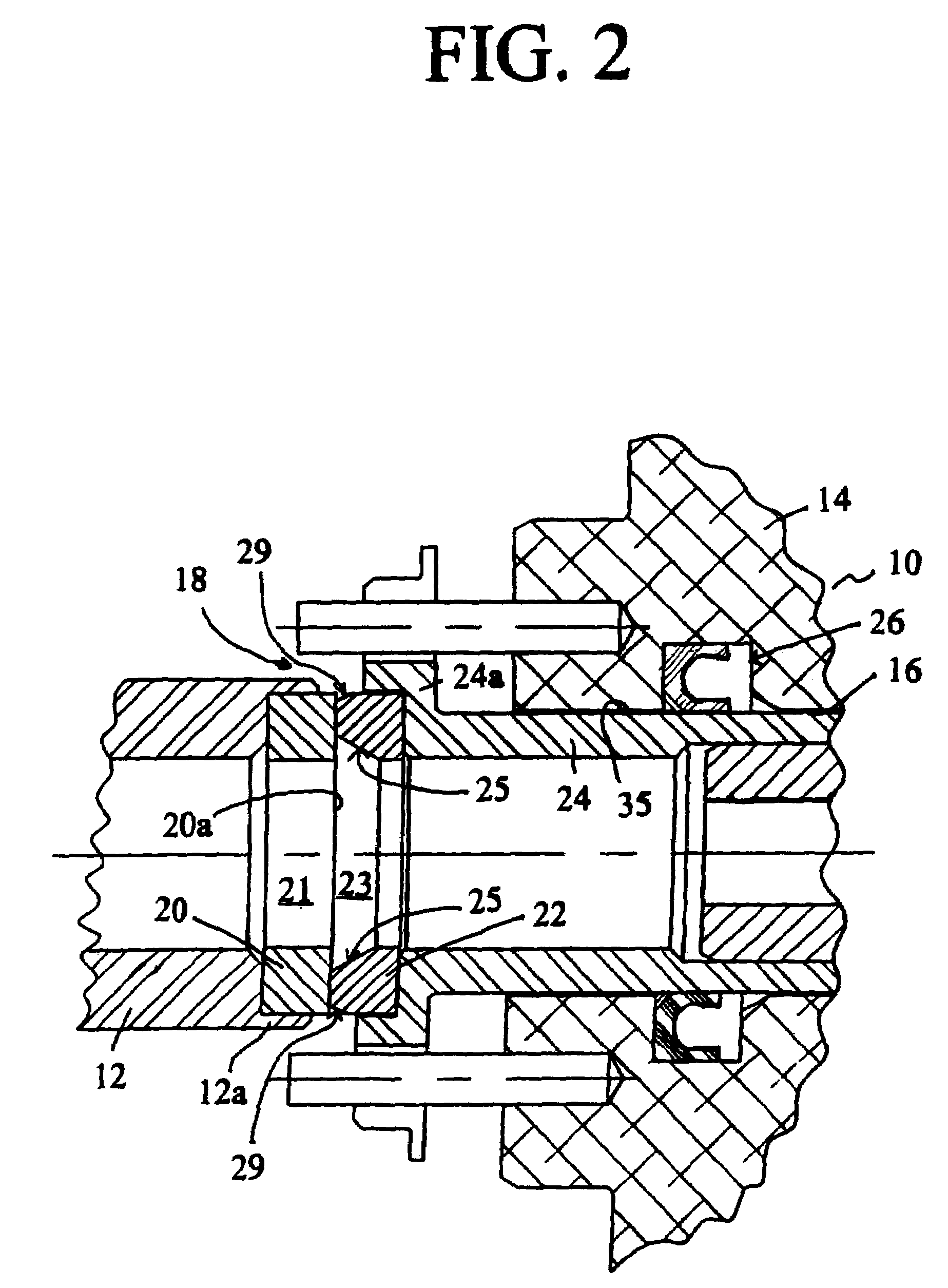
[0018]Referring now to the drawings wherein like numerals have been used throughout the several views to designate the same or similar parts, there is illustrated in the drawings a rotating fluid coolant union 10 incorporating the novel sealing arrangement in accordance with the present invention. The fluid coolant union 10, as shown in FIGS. 1 and 2, is utilized to conduct a fluid coolant either in a liquid or gaseous state from a source of coolant (not shown) to a spindle of a machine tool and the like. The spindle could be a machine tool used in the various applications such as machining centers, flexible transfer lines or any environment where fluid coolants such as water-based, oil-based, air-oil mist based and air-based coolants may be used in conjunction with the fluid coolant union 10.

[0019]The fluid coolant union 10 is comprised of a rotor or shaft member 12, coupled to an end cap or housing member 14. The end cap or housing 14 provides a cylindrical housing for the fluid c...


PUM


Abstract

A coolant union includes a seal assembly having a first seal member and a non-rotating second seal member. At least one of the annular sealing surfaces presented by the rotating seal member and the non-rotating seal member is chamfered such that the chamfered sealing surface presents a sealing surface width less than the width of the dimension of the other sealing surface. The fluid coolant union further includes a U-shaped annular secondary seal member having a chamfered portion structurally arranged to receive a triangular back-up ring which stores sufficient relative displacement of the floating seal assembly to create a separation between the first rotating seal and the second non-rotating seal members during the unpressurized condition.

Description

CROSS-REFERENCE TO RELATED PATENT APPLICATIONS[0001]This application claims priority to provisional patent application No. 60 / 435,890, filed on Dec. 20, 2002.BACKGROUND OF THE INVENTION[0002]The present invention relates to a fluid coupling union such as a fluid coolant rotating union having a secondary sealing assembly which provides a depressurized condition displacement of the floating seal members from one another to provide a pop-off or gap between the seal members when the cooling union is depressurized.[0003]Fluid coolant unions are used extensively in conjunction with machine tools in various high speed drilling and boring transfer operations, high speed machine tool spindles, and in various applications such as machining centers and flexible transfer lines. In such applications, the rotating union is structurally arranged to conduct various types of coolants, such as water-based, oil-based, and air-based fluids into the machine tool spindle. Preferably, such coolants may be...

Claims


Application Information

Patent Timeline
IPC IPC(8): F16L17/035F16J15/18F16L27/00F16J15/10B23Q11/12F16J15/34F16L27/08
CPCB23Q11/103F16L27/082B23Q11/12
Inventor KUBALA, ZBIGNIEW
Owner DEUBLIN
Why Eureka
Try Eureka