Molded plastic rod with improved break strength

a technology lateral break strength, which is applied in the field of molded plastic rods, can solve the problems of easy cracks, reduced overall break strength, and inability to withstand inborn stresses, and achieves the effects of improving lateral break strength, reducing cracks or breaking during shipment, installation and use, and increasing overall strength

Inactive Publication Date: 2007-06-12
ILLINOIS TOOL WORKS INC
View PDF5 Cites 0 Cited by
  • Summary
  • Abstract
  • Description
  • Claims
  • Application Information

AI Technical Summary

Benefits of technology

[0011]An advantage of the present invention is providing an injection-molded rod of increased overall strength.
[0012]Another advantage of the present invention is providing a plastic rod with improved lateral break strength at the injection point on any length of injection molded rod rod.
[0013]Still another advantage of the present invention is providing an injection molded plastic rod in which a sharp edge or point, if any, remaining at the injection molding site is shielded from contact with other items and things.
[0014]A further advantage of the present invention is providing an injection-molded rod that is less susceptible to cracking or breaking during shipment, installation and use.
[0015]Other features and advantages of the invention will become apparent to those skilled in the art upon review of the following detailed description, claims and drawings in which like numerals are used to designate like features.

Problems solved by technology

It has been observed that such injection-molded rods are susceptible to inborn stresses that are concentrated at the injection point.
The concentration of inborn stresses at the injection point weakens the overall strength of the rod, resulting in much reduced overall break strength.
The concentration of stresses in a relatively small area can cause cracks to form easily, which can then propagate quickly.
As a result, prior rods have been known to break during shipment or installation, and a cracked or weakened rod may even fail during use.
Another problem with known rods of this type is that a sharp point or edge may be developed at the injection point (gate), with residual material (gate vestige) extending above the surface of the rod.
A sharp or pointed gate vestige has the potential of damaging any product or item that comes in contact with it.
Removing the sharp point or edge involves a subsequent process to the molding process, which can be time consuming and may significantly increase the cost for the rod.

Method used


Image

  • Molded plastic rod with improved break strength
  • Molded plastic rod with improved break strength

Examples


Embodiment Construction

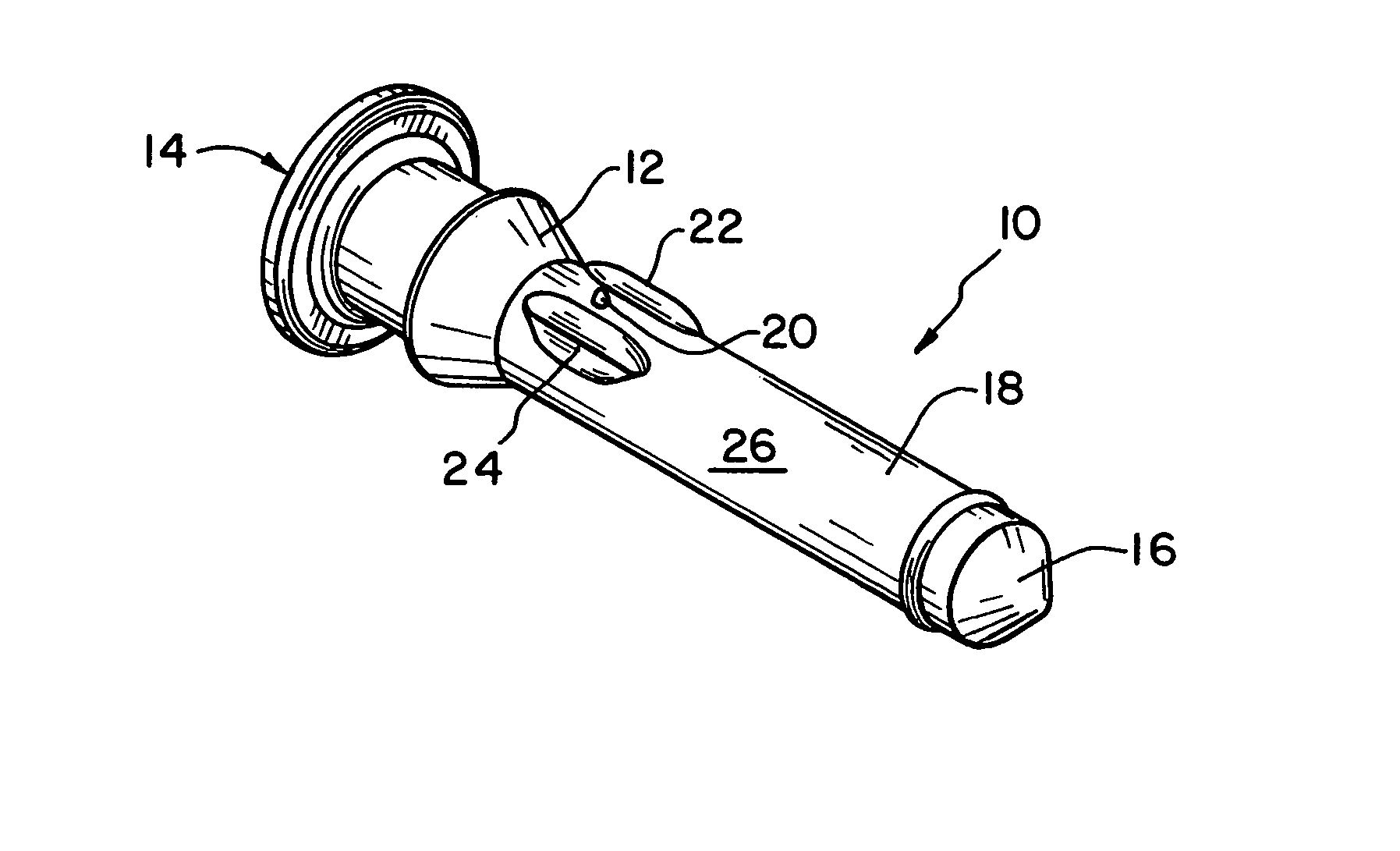
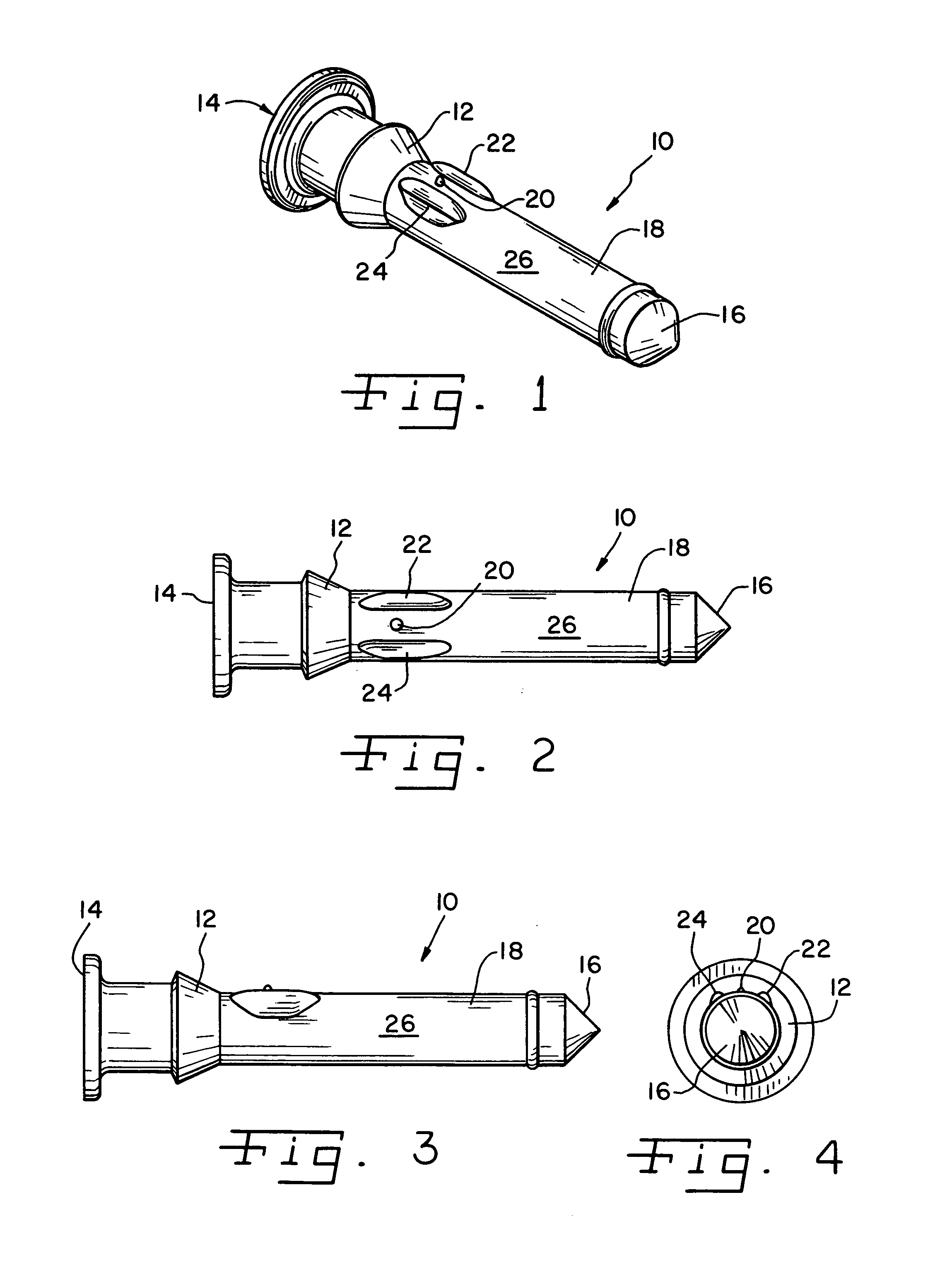
[0021]Referring now more specifically to the drawings and to FIG. 1 in particular, numeral 10 designates an injection molded plastic rod in accordance with the present invention. The exemplary rod 10 shown and described herein is a rod adapted for use in a battery hydrometer. The present invention is of particular advantage when used for the plastic rod of a battery hydrometer; however; it should be understood that the present invention can be used advantageously also in other applications and devices as well.

[0022]Rod 10 is a light transmissive rod made of light transmitting material, such as, for example, acrylic, styrene or other clear or partially clear material. Plastic rods of the present invention used for other, non-light transmissive applications can be made of other materials. The present invention works well with a variety of different injection-molded plastic materials, both light transmissive and non-light transmissive.

[0023]Exemplary rod 10 further includes a collar 12...


PUM

PropertyMeasurementUnit
angleaaaaaaaaaa
specific gravityaaaaaaaaaa
injection stressaaaaaaaaaa

Abstract

An injection molded plastic rod suitable for use in a battery hydrometer. Stress-relieving formations are provided symmetrically arranged on opposite sides of an injection gate of the rod. The formations distribute injection stresses and shield the gate vestige.

Description

CROSS-REFERENCE TO RELATED APPLICATIONS[0001]The present regular U.S. Patent Application claims the benefits of U.S. Provisional Patent Application Ser. No. 60 / 411,603, filed Sep. 18, 2002.FIELD OF THE INVENTION[0002]The present invention relates generally to molded plastic rods and, more particularly, the present invention relates to molded plastic rods used in battery hydrometers.BACKGROUND OF THE INVENTION[0003]Simple plastic rods are used in many devices and apparatuses. One use for molded plastic rods is in battery hydrometers. An elongated transparent plastic rod extends downwardly from the top of the battery into one or more cells of the battery. The rod has attached thereto a cage that encloses or suspends one or more spherical balls within the battery fluid. The hydrometer can monitor both the battery fluid level and the specific gravity of the battery fluid. Incident light rays are transmitted through the transparent rod, and various patterns or colors are transmitted to t...

Claims


Application Information

Patent Timeline
Patent Type & Authority Patents(United States)
IPC IPC(8): B29B7/00B29C45/00G01N9/00
CPCB29C45/0025Y10T428/249921
Inventor SUMMER, MARK J.
Owner ILLINOIS TOOL WORKS INC
Why Eureka
Try Eureka