Mass spectrometer

a mass spectrometer and mass spectrometer technology, applied in the field of mass spectrometers, can solve the problems of deteriorating the sensitivity of sample analysis, difficult to converge again to the orifice, and deflected ions, so as to improve the efficiency of ion passing through the hole, enhance the sensitivity of mass analysis, and increase the number of ions

Inactive Publication Date: 2007-06-12
SHIMADZU CORP
View PDF9 Cites 11 Cited by
  • Summary
  • Abstract
  • Description
  • Claims
  • Application Information

AI Technical Summary

Benefits of technology

[0007]In view of the above described problems, an object of the present invention is to improve the sensitivity of a mass spectrometer using an API interface by making more ions pass the intermediate vacuum chambers while preventing unnecessary residual gas molecules from doing the same.
[0016]With the conventional ion lens, once an ion collides with a residual gas molecule and is deflected, it is difficult to force it back to the original course for leading ions to pass through the hole. According to the present invention, a deflected ion can be pulled back toward the hole owing to the AC electric field generated near the hole. This improves the ion passing efficiency through the hole, and increases the number of ions reaching the mass filter and ion detector, which of course enhances the sensitivity of the mass analysis.

Problems solved by technology

If an ion being converged by the ion lens contacts a residual gas molecule, the ion is deflected and is difficult to converge again to the orifice with the electric field by the ion lens alone.
This deteriorates the sensitivity of the sample analysis.

Method used


Image

  • Mass spectrometer
  • Mass spectrometer
  • Mass spectrometer

Examples


Embodiment Construction

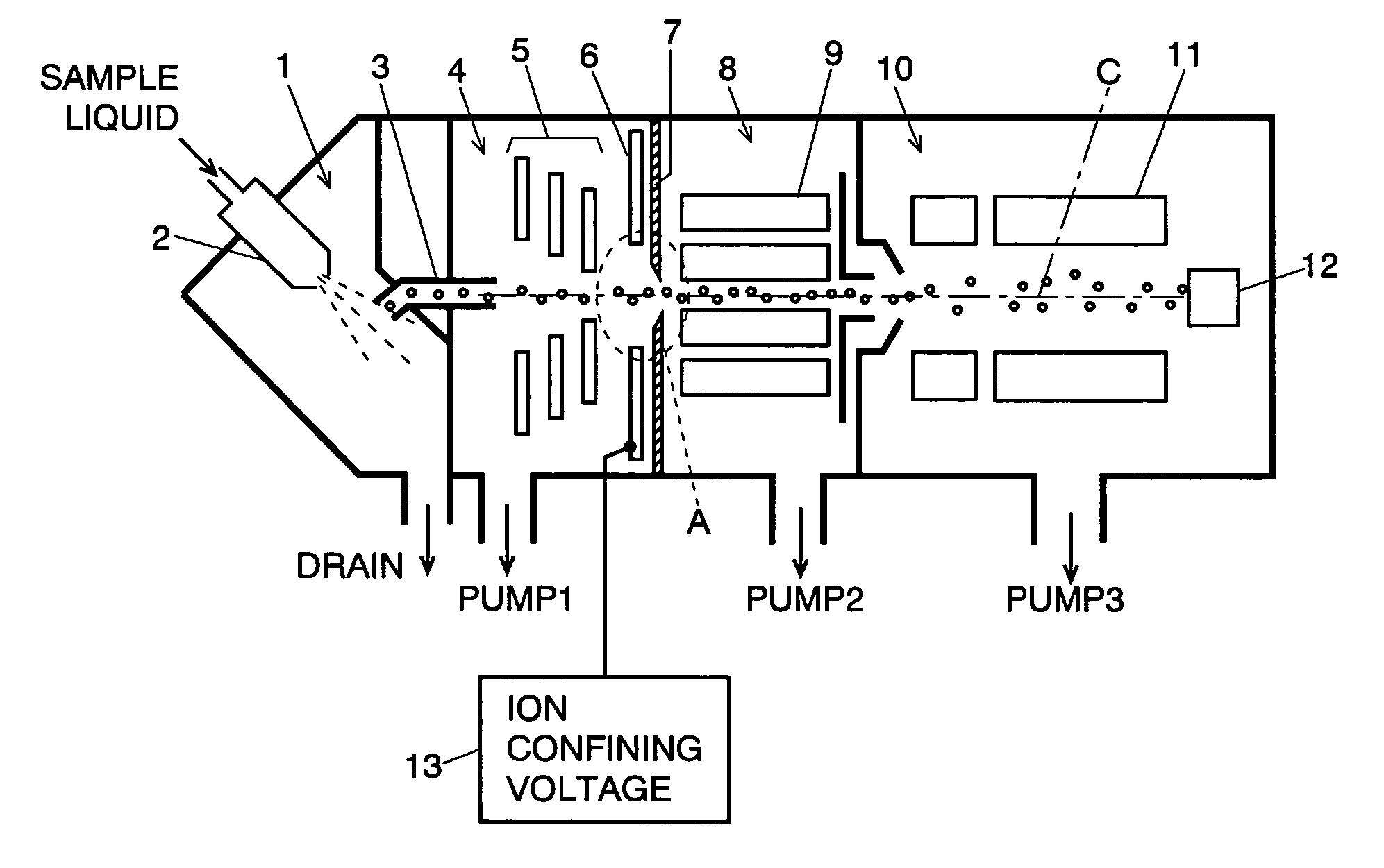
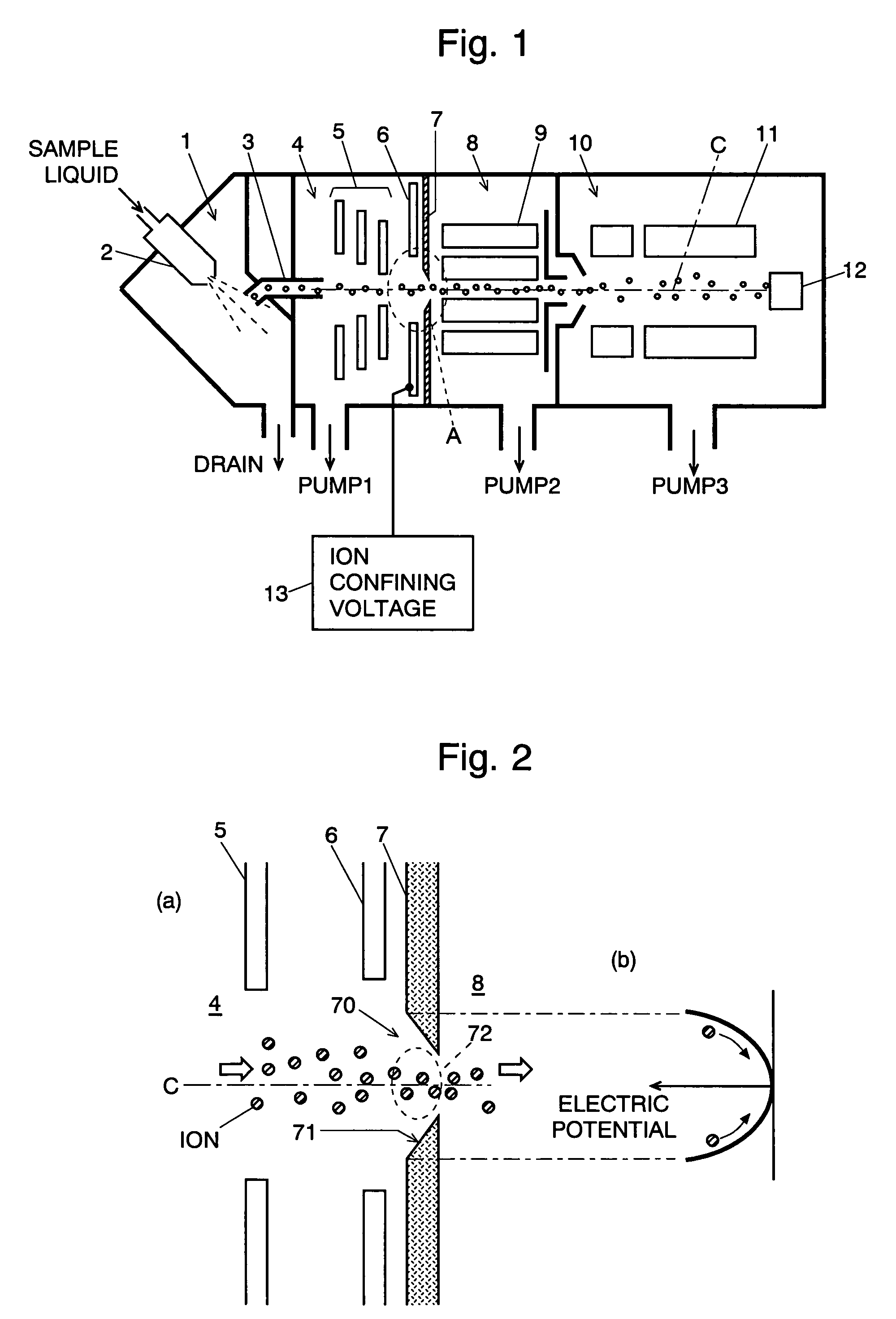
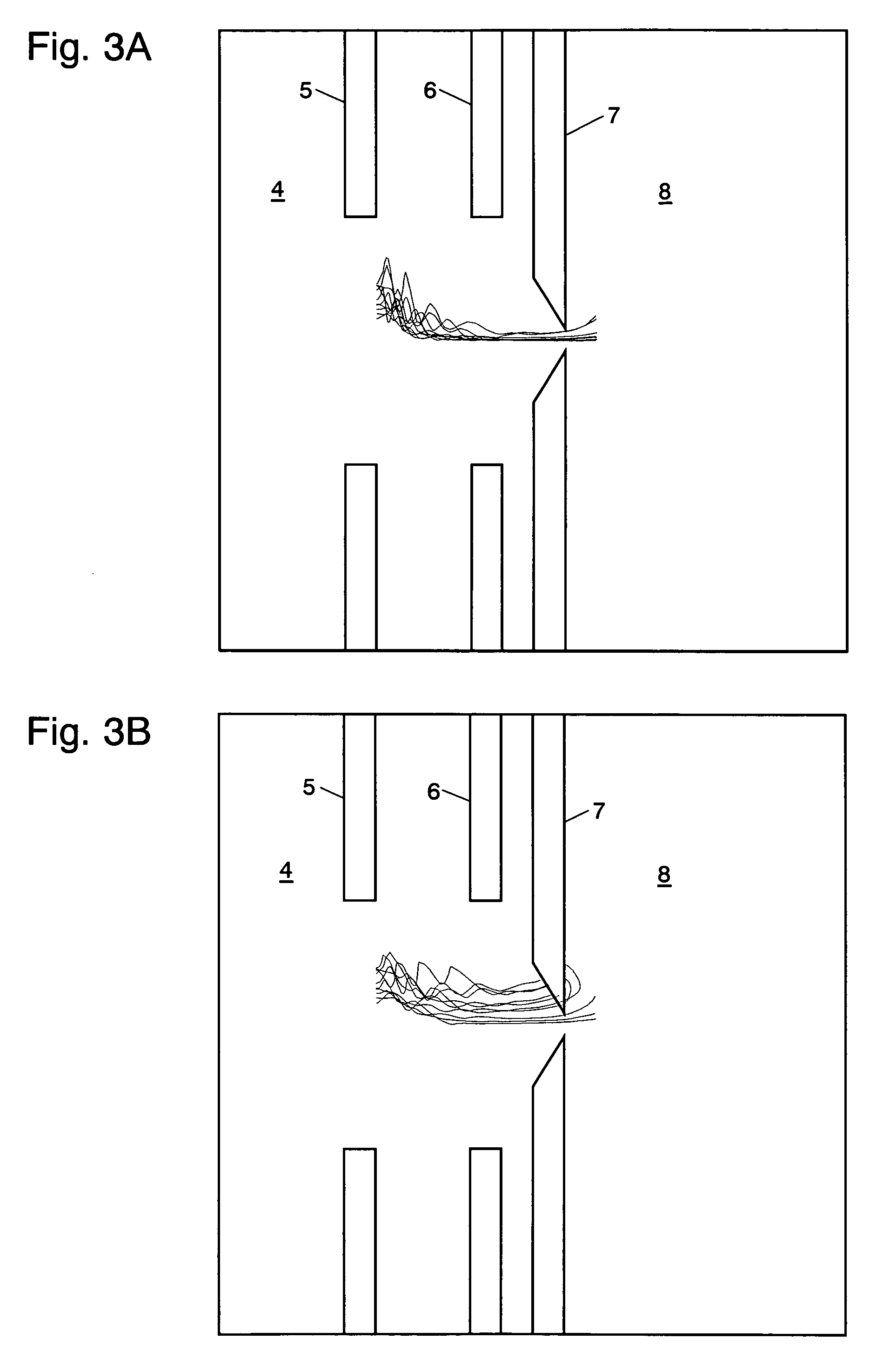
[0023]A mass spectrometer using an ESI interface embodying the present invention is described using the accompanying drawings. Though not shown in FIG. 1, a liquid chromatograph is attached to the mass spectrometer, wherein the exit of the column of the liquid chromatograph is connected to the nozzle 2 of the ionizing chamber 1. In the mass spectrometer, a first intermediate vacuum chamber 4 and a second intermediate vacuum chamber 8 are provided between the ionizing chamber 1 and a mass analyzing chamber 10 in which a quadrupole mass filter 11 and an ion detector 12 are accommodated. The chambers 1, 4, 8 and 10 are separated by respective walls, wherein the wall between the ionizing chamber 1 and the first intermediate vacuum chamber 4 is equipped with a dissolvation line 3, and the wall 7 between the first intermediate vacuum chamber 4 and the second intermediate vacuum chamber 8 has an orifice 70. The inner diameters of both the dissolvation line 3 and the orifice 70 are rendered...


PUM

PropertyMeasurementUnit
pressureaaaaaaaaaa
pressureaaaaaaaaaa
mass spectrometeraaaaaaaaaa

Abstract

A mass spectrometer adopting a differential pumping system includes an ionization chamber with substantially atmospheric pressure, two intermediate vacuum chambers, and a mass analyzing chamber with a very low pressure (or a very high vacuum), where the pressures of these chambers are in the order of higher to lower. A hole is provided in every wall between two adjoining chambers for allowing ions to be mass analyzed to pass through. An auxiliary electrode with an aperture is placed near the hole, and an AC voltage is applied to the auxiliary electrode. Owing to an AC electric field generated by the AC voltage around the hole, an ion coming near the hole is exerted with such a force that confines the ion to the ion optical axis C. Under these circumstances, even when the ion collides with a residual gas molecule or atom and is deflected away from the ion optical axis, the confining force exerted by the electric field pulls the ion back toward the ion optical axis. This improves the ion passing efficiency of the hole, and increases the number of ions reaching the mass filter and ion detector, which consequently enhances the sensitivity of the mass analysis.

Description

[0001]The present invention relates to a mass spectrometer, specifically to one that has a differential pumping system, such as an atmospheric pressure ionizing mass spectrometer.BACKGROUND OF THE INVENTION[0002]Mass spectrometers are often used in combination with a liquid chromatograph or a gas chromatograph. In the case of a mass spectrometer combined with a liquid chromatograph (LCMS), the mass spectrometer is used as the detector of the liquid chromatograph. In the liquid chromatograph, a sample liquid containing components to be detected is made to flow through a liquid chromatograph column, where the components are separated with respect to time while the sample passes through the column. The liquid (eluate) flowing out of the column is ionized by an interface, and the ionized component atoms or molecules are introduced into the mass spectrometer where the ions are separated by their mass to charge ratios. Ions of the components thus separated in the mass spectrometer are det...

Claims


Application Information

Patent Timeline
Patent Type & Authority Patents(United States)
IPC IPC(8): H01J49/00G01N27/62H01J49/04H01J49/06H01J49/24
CPCH01J49/067
Inventor UENO, YOSHIHIRO
Owner SHIMADZU CORP
Why Eureka
Try Eureka