Electric motor with poles shaped to minimize cogging torque

a technology of electric motors and poles, applied in the field of electric motors, can solve the problems of high specific weight (weight/power ratio), unfavorable power to motor volume or motor power to motor weight, and insufficient power of such motors with ironless stators

Inactive Publication Date: 2007-06-12
EBM PAPST ST GEORGEN & -
View PDF25 Cites 46 Cited by
  • Summary
  • Abstract
  • Description
  • Claims
  • Application Information

AI Technical Summary

Benefits of technology

[0008]It is therefore an object of the invention to provide a sufficiently powerful internal rotor motor with minimized cogging torque. According to the invention, this object is achieved by careful shaping of cavities, formed in the rotor adjacent each circumferential end of the permanent magnets, and extending into undersides of the pole shoes, thereby giving each pole shoe a kind of mortarboard shape. One thereby obtains a multi-phase electric motor, in whose rotor one can use magnets whose angular span is not much smaller than a pole pitch of the rotor, and which nevertheless results in an induced voltage having a good sinusoidal form and an acceptable cogging torque. This makes it possible to improve the specific weight of such motors, i.e., for the same power, it suffices to use a motor which is smaller and lighter than before.

Problems solved by technology

In the context of many drive applications, this reluctance torque is disruptive, so that there one is forced to use so-called “ironless” stator windings in which no reluctance torque arises.
However, the power of such motors with ironless stators is generally insufficient because their air gap is very large.
This leads to a high “specific weight” (weight / power ratio), i.e. the relationship of motor power to motor volume or motor power to motor weight is unfavorable with them.
Some have tried to overcome this problem by giving the pole shoes of the rotor a particular form, but that has led, thus far, to a structure in which the specific weight was unfavorable.

Method used


Image

  • Electric motor with poles shaped to minimize cogging torque
  • Electric motor with poles shaped to minimize cogging torque
  • Electric motor with poles shaped to minimize cogging torque

Examples


Embodiment Construction

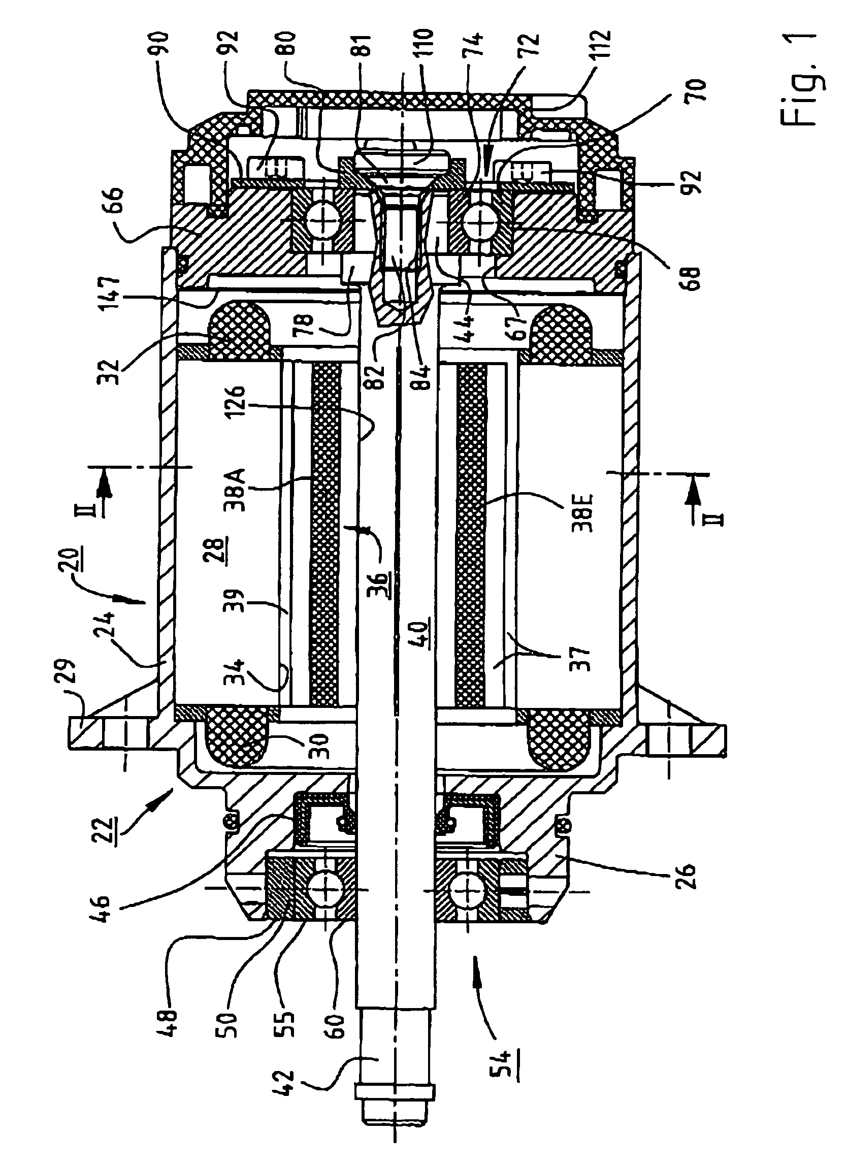
[0016]FIG. 1 shows an electronically commutated internal rotor motor 20 with a housing 22 having a cylindrical housing portion 24, an A-side bell 26 and a securing flange 29.

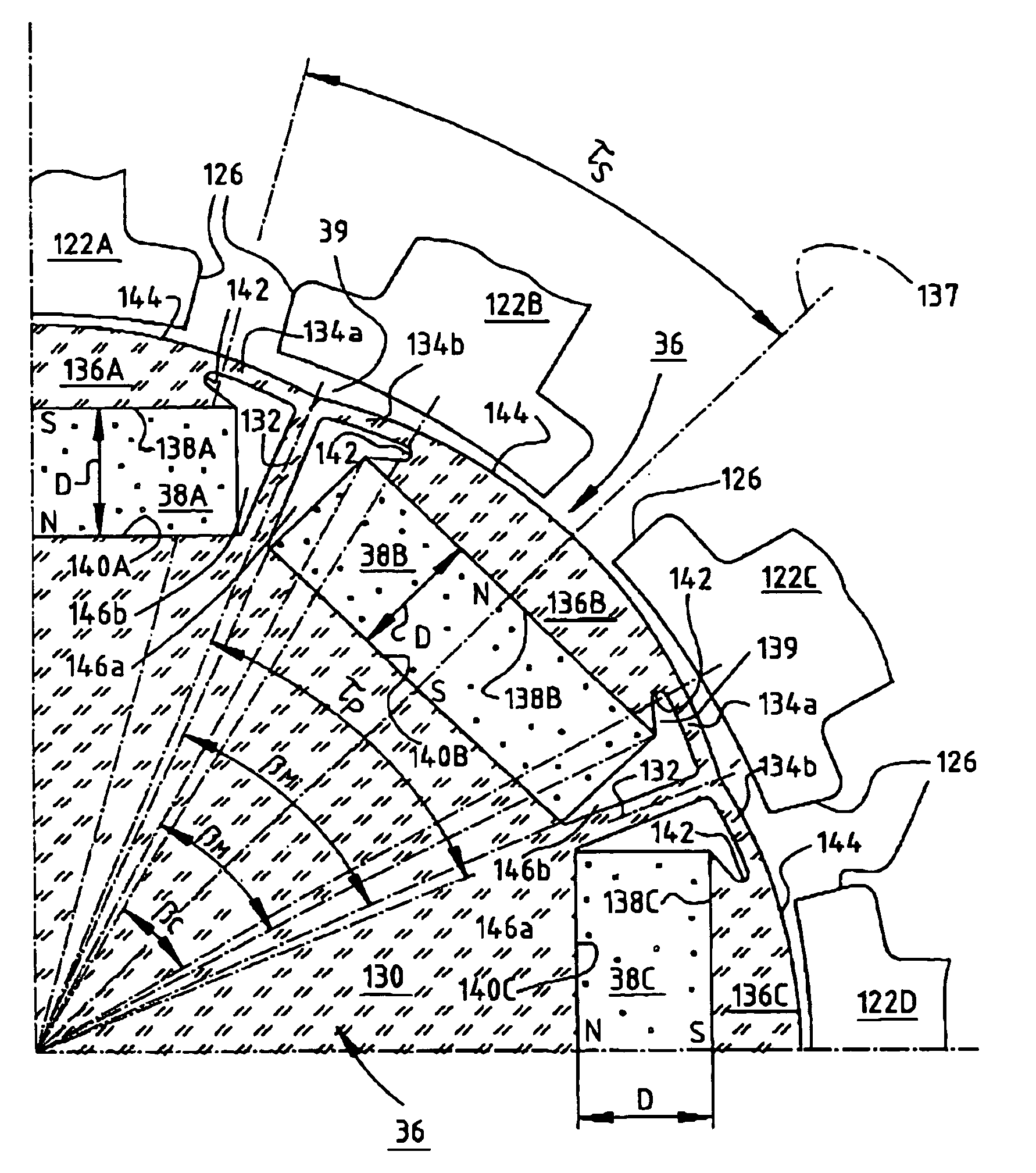
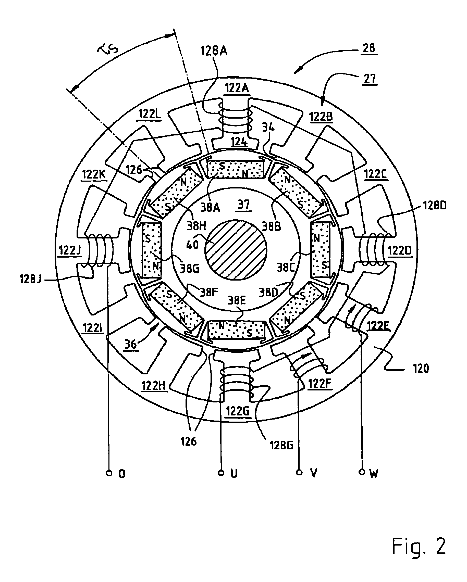
[0017]In the cylindrical housing portion 24, there is arranged the lamination stack 27 (FIG. 2) of an external stator 28 whose coil ends are designated 30 and 32. Stator 28 has an internal recess 34 in which is arranged an eight-pole internal rotor 36 having a lamination stack 37 made of an alloy according to German Industrial Standard DIN 46400, sheet 1, preferably alloy V400. Preferably, eight permanent magnets 38A through 38H (see FIGS. 2–3) are arranged on a shaft 40, whose drive end is designated 42 and whose inside shaft end is designated 44. An air gap 39 separates stator 28 from rotor 36. Such a motor can be called a “permanently excited synchronous internal rotor machine” or a “three-phase motor with impressed sinusoidal currents.”

[0018]In the A-side bell 26, in the usual manner, a seal 46 is provided f...


PUM


Abstract

An electric motor has a rotor (36) and a stator (28) having a lamination stack formed with slots (126). The slots have a predetermined slot pitch (τs), and a multi-phase stator winding is arranged in them. The rotor (36) has salient poles having pole shoes (136) and a magnetic return path (130). Between the return path (130) and each pole shoe (136), a recess (138, 140) is formed for receiving a permanent magnet (38). On each side of such a permanent magnet (38), a region (146a, 146b) of poor magnetic conductivity is arranged, in order to make the flux distribution in the air gap more sinusoidal. Measuring in a circumferential direction, the width (β) of a pole shoe (136) decreases with increasing distance from an interface (138) between said return path and said permanent magnet (38), and, at a place of lowest width, the pole shoe has an angular extent (βc) which has, with respect to the slot pitch (τs) between said stator slots (126), the following relationship:βc=n*τs*(1−0.02) . . . n*τs*(1−0.2),where n=1, 2, 3 . . . andβc and τs are measured in mechanical degrees.

Description

CROSS-REFERENCE TO RELATED APPLICATIONS[0001]This application is a continuation-in-part of my U.S. Ser. No. 10 / 390,824, filed 18 Mar. 2003 now U.S. Pat. No. 6,919,663. This application claims priority of German application DE 203 17 021.0, filed 5 Nov. 2003 and of European application 04 020 696.3, filed 1 Sep. 2004. The parent US application claims priority of German application DE 202 04 660.5, filed 22 Mar. 2002. The contents of all of these priority applications are hereby incorporated by reference.FIELD OF THE INVENTION[0002]The present invention relates to an electric motor, which preferably is configured as an internal rotor motor.BACKGROUND[0003]Such motors, preferably employing electronic commutation, are used, because of their low axial moment of inertia, for jobs where an electric motor's RPM must very quickly respond to electrical commands, e.g. for fast positioning of parts, or servo-assistance to movements. For this purpose, one desires such a motor to have a very unif...

Claims


Application Information

Patent Timeline
Patent Type & Authority Patents(United States)
IPC IPC(8): H02K21/12H02K1/27H02K21/16H02K29/03
CPCH02K1/276H02K21/16H02K29/03
Inventor ILES-KLUMPNER, DORIN
Owner EBM PAPST ST GEORGEN & -
Why Eureka
Try Eureka