
Ultrafast laser pulse shape measurement method and system

a laser pulse and ultrafast technology, applied in the direction of measurement devices, instruments, using optical means, etc., can solve the problems of inability to temporally resolve the pulse produced by ultrafast lasers, inability to achieve the shape determination of ultrafast laser pulses, and inability to achieve picosecond laser pulses as well as the frog techniqu

Inactive Publication Date: 2007-06-12
PANASONIC CORP
View PDF5 Cites 11 Cited by
  • Summary
  • Abstract
  • Description
  • Claims
  • Application Information

AI Technical Summary

Benefits of technology

This approach provides accurate measurement of pulse shapes for a broad range of pulse widths, including picosecond pulses, by effectively capturing phase and intensity information, overcoming the limitations of existing techniques.

Problems solved by technology

Direct measurement techniques using photodetectors and oscilloscopes are inadequate to temporally resolve the pulses being produced by ultrafast lasers, typically less than 1 ns in duration.
Therefore this approach is not desirable for determining the shape of ultrafast laser pulses.
However, FROG techniques do not work as well for picosecond laser pulses.
For example, a transform-limited 20 ps laser pulse at 1053 nm has a bandwidth of 0.1 nm, which may be difficult to resolve accurately using a spectrometer.
This method works well for longer pulses, but may have difficulties with obtaining highly precise and accurate pulse shape measurements for pulse widths less that about 1 ns due to jitter in the timing circuitry of the camera.
Improvements in these circuits may extend the range of this method, but some jitter is likely to remain.

Method used


Image

  • Ultrafast laser pulse shape measurement method and system
  • Ultrafast laser pulse shape measurement method and system
  • Ultrafast laser pulse shape measurement method and system

Examples


Embodiment Construction

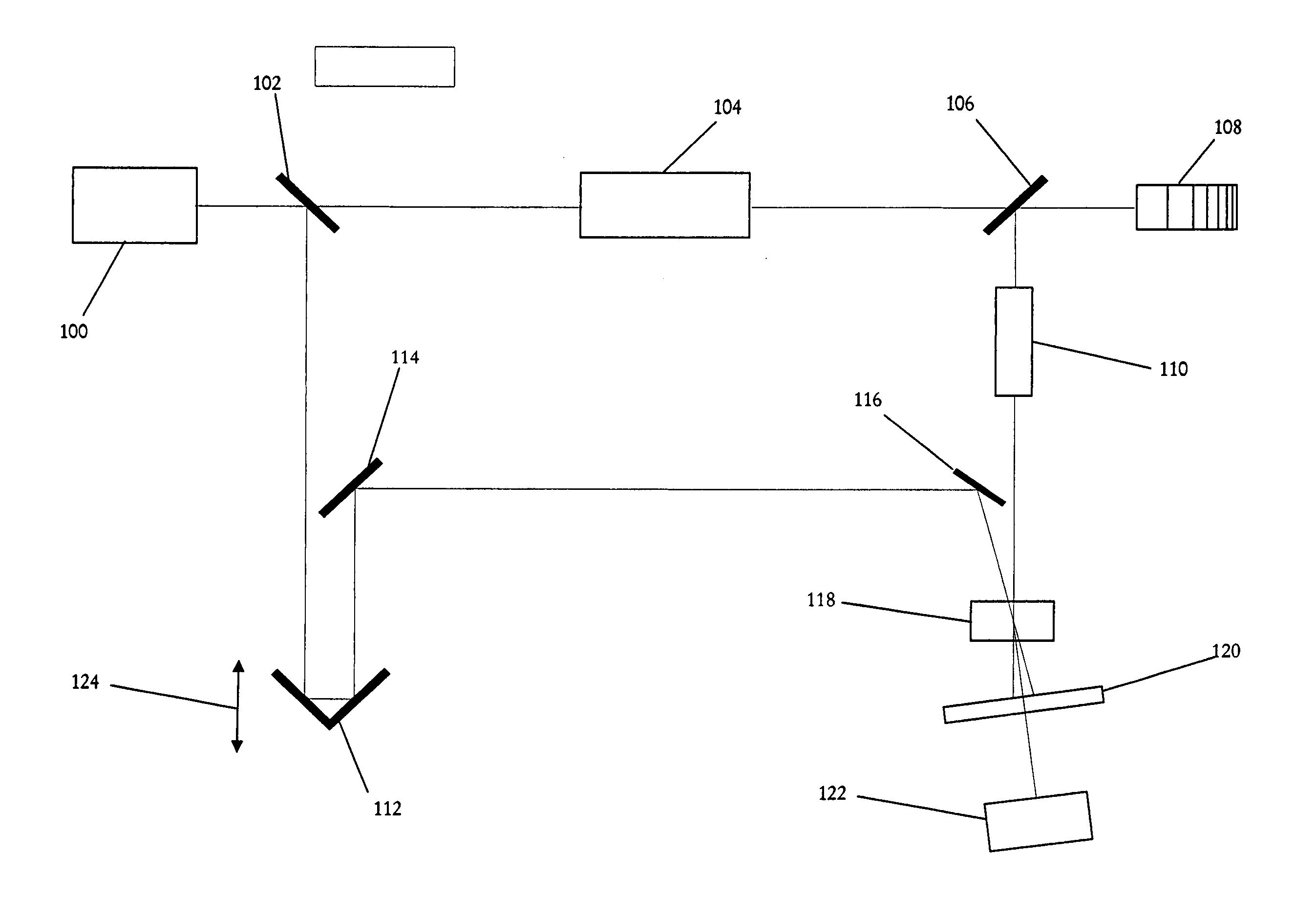
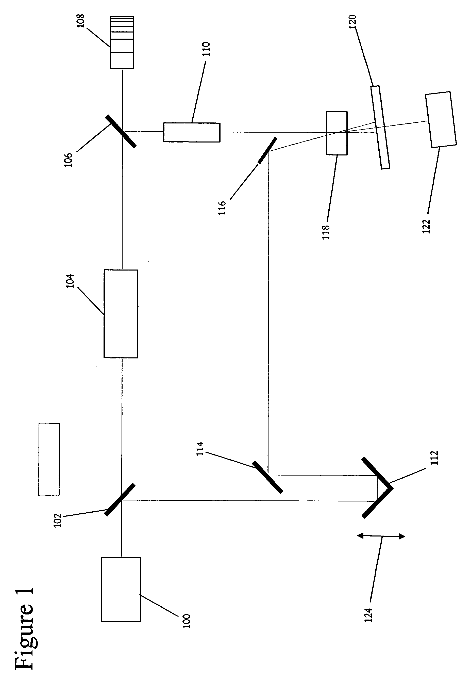
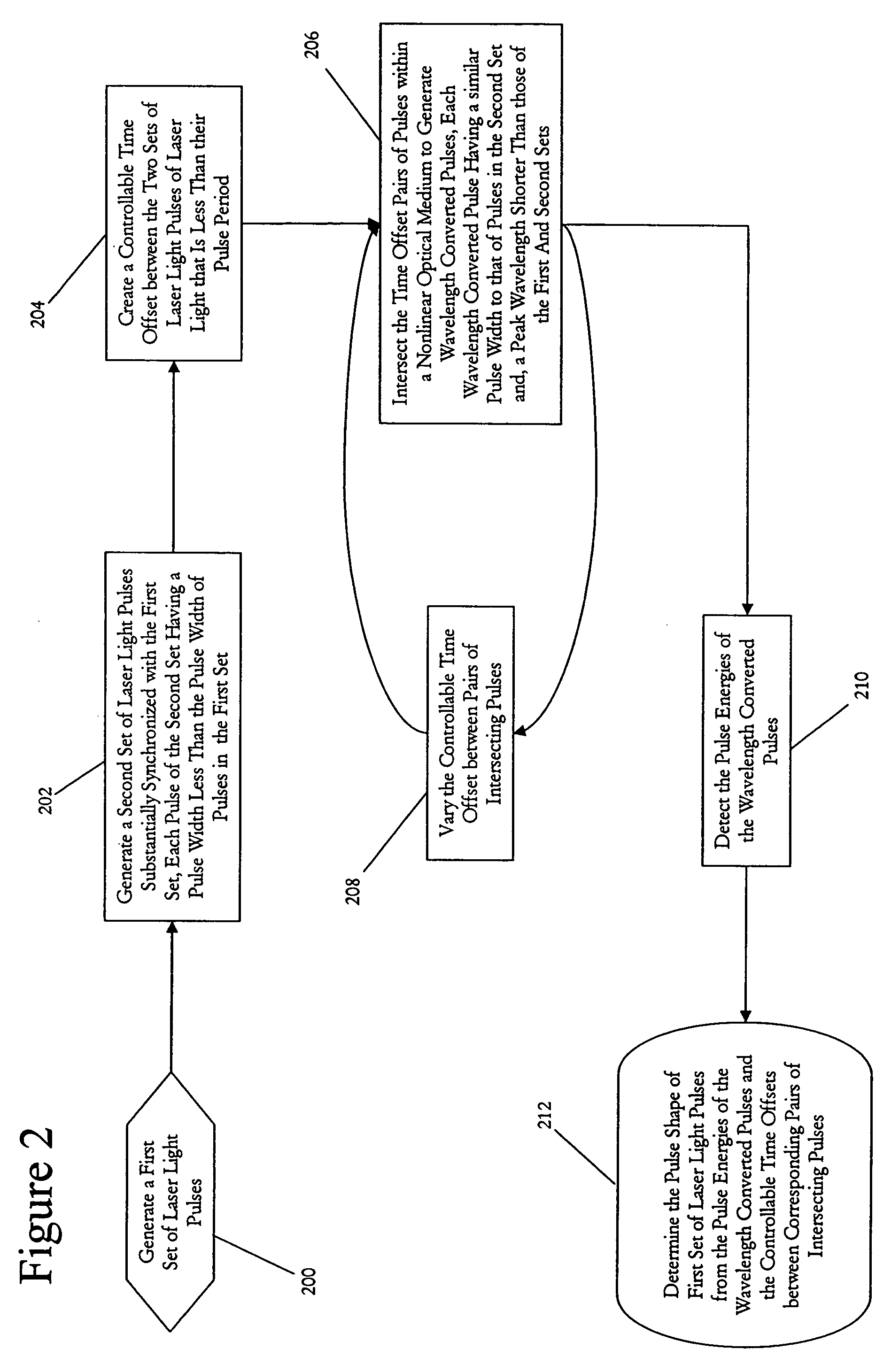
[0016]As described above, a typical autocorrelation technique does not allow the pulse shape to be resolved and a FROG technique works best for shorter duration pulses that have relatively wide wavelength bandwidths. Therefore, a different approach is desirable for laser pulses with pulse widths, durations, in the range of about 100 fs to 1 ns.

[0017]The present invention provides such an approach, the use of a cross-correlation technique to measure the pulse shape, and duration. An autocorrelation technique is a correlation of two beams, the electric fields of which are identical or are proportional. One common way to perform an autocorrelation is for one beam to be split into two beams, and the then two beams are recombined with a controllable time offset. Equation (1) shows that the intensity of the autocorrelation is a convolution of the electric field for the first beam, E, with the electric field for the second beam, which is also E. In contrast, a cross-correlation is correlat...


PUM


Abstract

A laser pulse shape measuring system to measure the pulse shape of pulses generated by a pulsed laser. Each pulse includes a pulse width and a peak wavelength. The system includes: a beam splitter coupled to the laser to separate each of the pulses into a test pulse and a probe pulse; a pulse width compression means coupled to the beam splitter to compress the pulse width of each probe pulse; a controllable delay means to control a time offset between each test pulse and a corresponding probe pulse; a nonlinear optical medium arranged such that the test beam path and the probe beam path intersect within it to generate wavelength converted pulses corresponding to intersecting pairs of pulses; a detector coupled to the nonlinear optical medium to detect the pulse energies of the wavelength converted pulses; and a processor to determine the pulse shape of the laser pulses.

Description

FIELD OF THE INVENTION[0001]The present invention relates generally to methods and systems for measuring the temporal pulse shape of pulses of laser light from ultrafast laser. More particularly these methods and systems may be used to provide simplified measurements of the pulse shapes of pulses of laser light having pulse durations of in the picosecond range.BACKGROUND OF THE INVENTION[0002]The invention of ultrafast lasers in 1965 led to the desire for new techniques to measure the duration of ultrashort optical pulses. Direct measurement techniques using photodetectors and oscilloscopes are inadequate to temporally resolve the pulses being produced by ultrafast lasers, typically less than 1 ns in duration. An indirect technique with subpicosecond time resolution has been proposed and demonstrated, however. This technique is based on the nonlinear process of second-harmonic generation (SHG). The optical pulse is divided into two beams, which travel different paths before being re...

Claims


Application Information

Patent Timeline
Patent Type & Authority Patents(United States)
IPC IPC(8): G01B9/02
CPCG01J11/00
Inventor LI, MING
Owner PANASONIC CORP
Learn More