
Three-dimensional measuring apparatus for scanning an object and a measurement head of a three-dimensional measuring apparatus and method of using the same

a three-dimensional measuring and object technology, applied in the direction of distance measurement, instruments, using reradiation, etc., can solve the problem that the related technology cannot meet the needs, and achieve the effect of optimizing the scanning range to be very larg

Inactive Publication Date: 2007-06-12
SPECIALITY MINERALS (MICHIGAN) INC
View PDF11 Cites 15 Cited by
  • Summary
  • Abstract
  • Description
  • Claims
  • Application Information

AI Technical Summary

Benefits of technology

Enables efficient measurement of wear profiles on metallurgical vessels with improved scanning range and reduced size, protecting thermosensitive components from harsh conditions, allowing for precise and extended measurement capabilities.

Problems solved by technology

However, the location, interrelation and direction of components in the related art is such that related technology is not able to fulfill the needs regarding the compatibility to detrimental conditions, regarding the scanning range and regarding the size of the apparatus and the size of the measurement head.

Method used


Image

  • Three-dimensional measuring apparatus for scanning an object and a measurement head of a three-dimensional measuring apparatus and method of using the same
  • Three-dimensional measuring apparatus for scanning an object and a measurement head of a three-dimensional measuring apparatus and method of using the same
  • Three-dimensional measuring apparatus for scanning an object and a measurement head of a three-dimensional measuring apparatus and method of using the same

Examples


Embodiment Construction

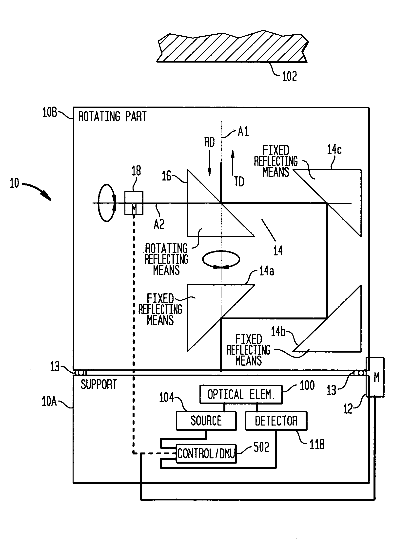
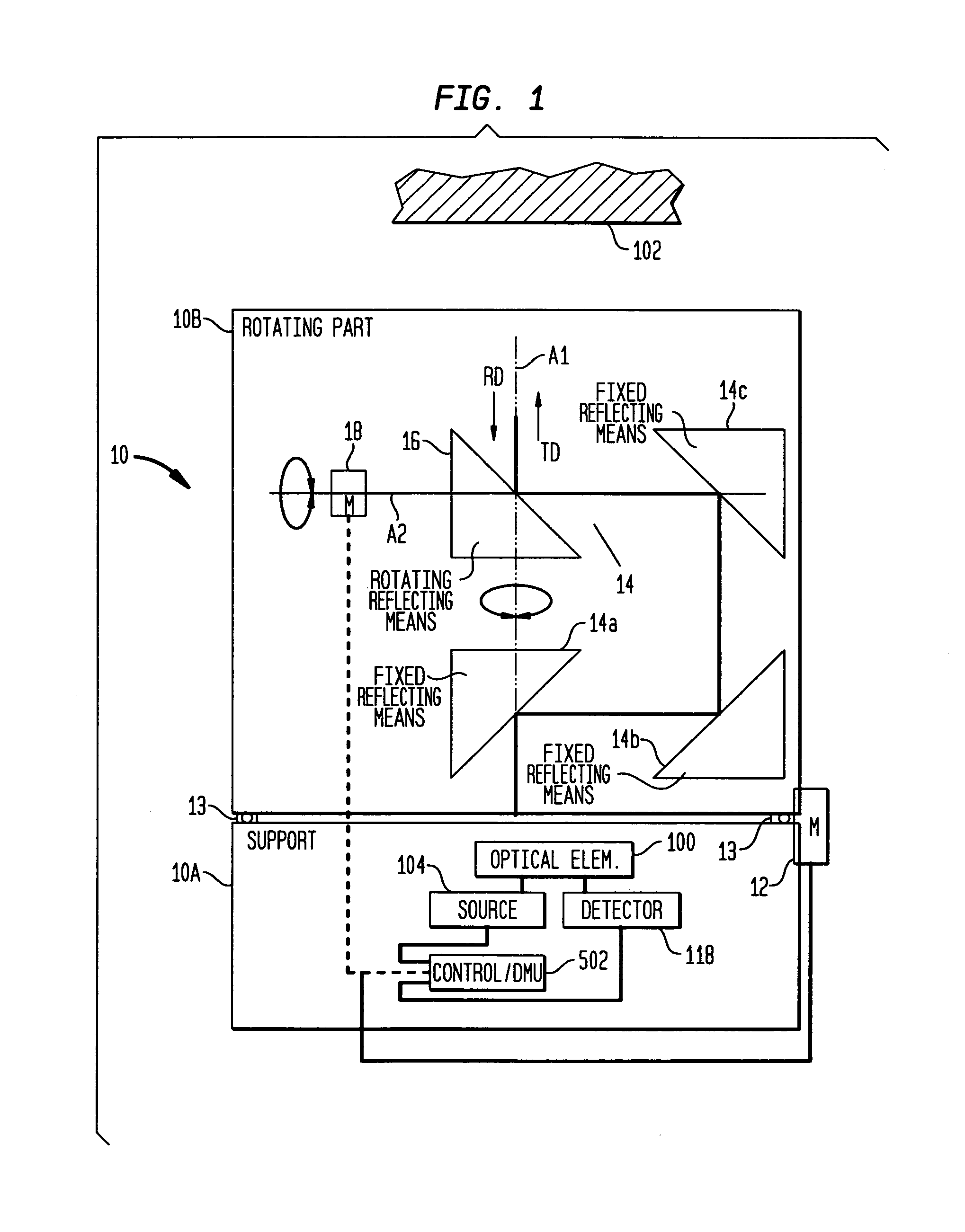
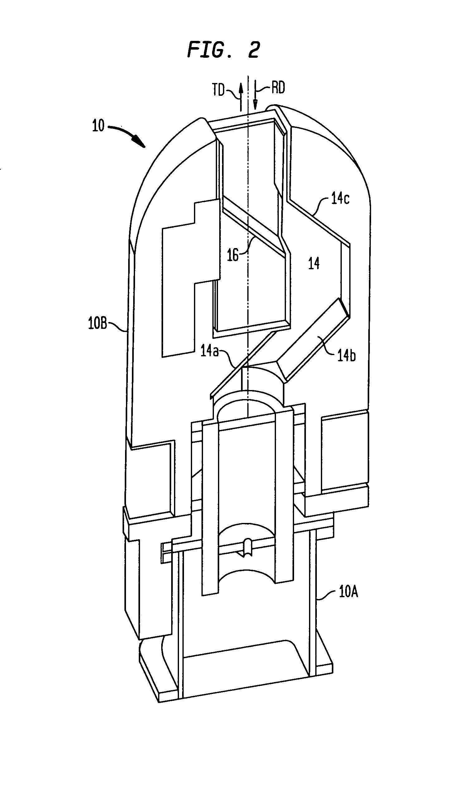
[0024]With reference to FIG. 1 and FIG. 2, a three-dimensional measuring apparatus for scanning an object 102 is shown. The apparatus comprises a measurement head 10 (including a support 10A and a rotatable part 10B), an optical source 104 for creating the optical beam to be transmitted through the measurement head 10 in the transmission direction (TD), a stop detector 118 for receiving the optical beam through the measurement head 10 in the reception direction (RD) and also a distance measurement unit for controlling the operation of the apparatus and for calculating the distance being measured.

[0025]The apparatus is configured to transmit an optical beam towards an object 102 in a transmission direction (TD) through a measurement head 10, and to receive an optical beam reflected from the object 102 in a reception direction (RD) through the measurement head 10.

[0026]The apparatus may also comprise an optical element 100, the role of the optical element 100 being to separate the opt...


PUM

PropertyMeasurementUnit
wavelength bandaaaaaaaaaa
angleaaaaaaaaaa
opticalaaaaaaaaaa

Abstract

An improved three-dimensional (3D) measuring apparatus for scanning an object and a measurement head of a measuring apparatus and a method for using the measuring apparatus for scanning an object.

Description

BACKGROUND OF THE INVENTION[0001]The invention relates to measuring of three-dimensional (3D) properties.[0002]A distance measuring apparatus can be a range finder based on a time-of-flight principle, e.g. using a pulsed laser beam. A laser of the measuring apparatus having a suitable optical arrangement transmits an optical beam towards a desired object. The optical beam is reflected from the object to a receiver or detector that has a suitable optical arrangement for receiving. The duration for the optical beam to travel from the measuring apparatus to the object and back can be measured and the measured result can be transformed into distance on the basis of the speed of light.[0003]One use of distance measurement is to measure the wear of the linings of metallurgical vessels, including, but not limited to, converter or ladle linings. In this context, knowledge of the thickness of the refractory lining—also called “remaining refractory thickness”—permits effective utilization of ...

Claims


Application Information

Patent Timeline
Patent Type & Authority Patents(United States)
IPC IPC(8): G01B11/24G01N21/86
CPCG01B11/24G01S7/4811G01S17/89
Inventor JOKINEN, HANNU ENSIOKIRCHHOFF, STEFANCARLHOFF, CHRISTOPH
Owner SPECIALITY MINERALS (MICHIGAN) INC
Learn More