Minimum latency cut-through switch fabric

a switch fabric and low latency technology, applied in the field of packet communication switching, can solve the problems of lack of flexibility, lack of available addresses, poor security features, etc., and achieve the effect of minimal latency

Inactive Publication Date: 2007-06-12
QUALCOMM INC
View PDF4 Cites 104 Cited by
  • Summary
  • Abstract
  • Description
  • Claims
  • Application Information

AI Technical Summary

Problems solved by technology

The obvious disadvantage of a switch fabric hardwired to handle a specific protocol is lack of flexibility.
For example, TCP / IP, the machine language of Internet routers, now runs primarily “IPv4.” This protocol, successful as it has been, has a lack of available addresses, poor security features, and no “quality of service” (QoS) provisions.
The disadvantage of a protocol agnostic switch fabric is that it may be more complicated, and perhaps slower than a switch fabric dedicated to a particular protocol.
the interface between the TM and switch fabric is more complicated.
It was then believed that variable length (multi-cell) packets would be too difficult to implement at rates needed for wire-speed traffic.
Large frames and concomitant switching latencies can render a switch useless for most 2-way voice applications.
Voice communications require low latency (time delay).
Since ATM had to work for all network data, the small payload (voice) requirements prevailed at the expense of the large frame applications.
These switch fabrics have generally not been used for voice data because of the large latency.
Such communications are very high speed and bursty, with non-critical latency constraints.
The problem with the store-and-forward method is the added latency of buffering the packet.
The problem with these switch fabrics is that they become prohibitively expensive and large from all the required high-speed memory.
Such fabrics cannot be used to reach terabit total switching speeds with technology available today.

Method used


Image

  • Minimum latency cut-through switch fabric
  • Minimum latency cut-through switch fabric
  • Minimum latency cut-through switch fabric

Examples


Embodiment Construction

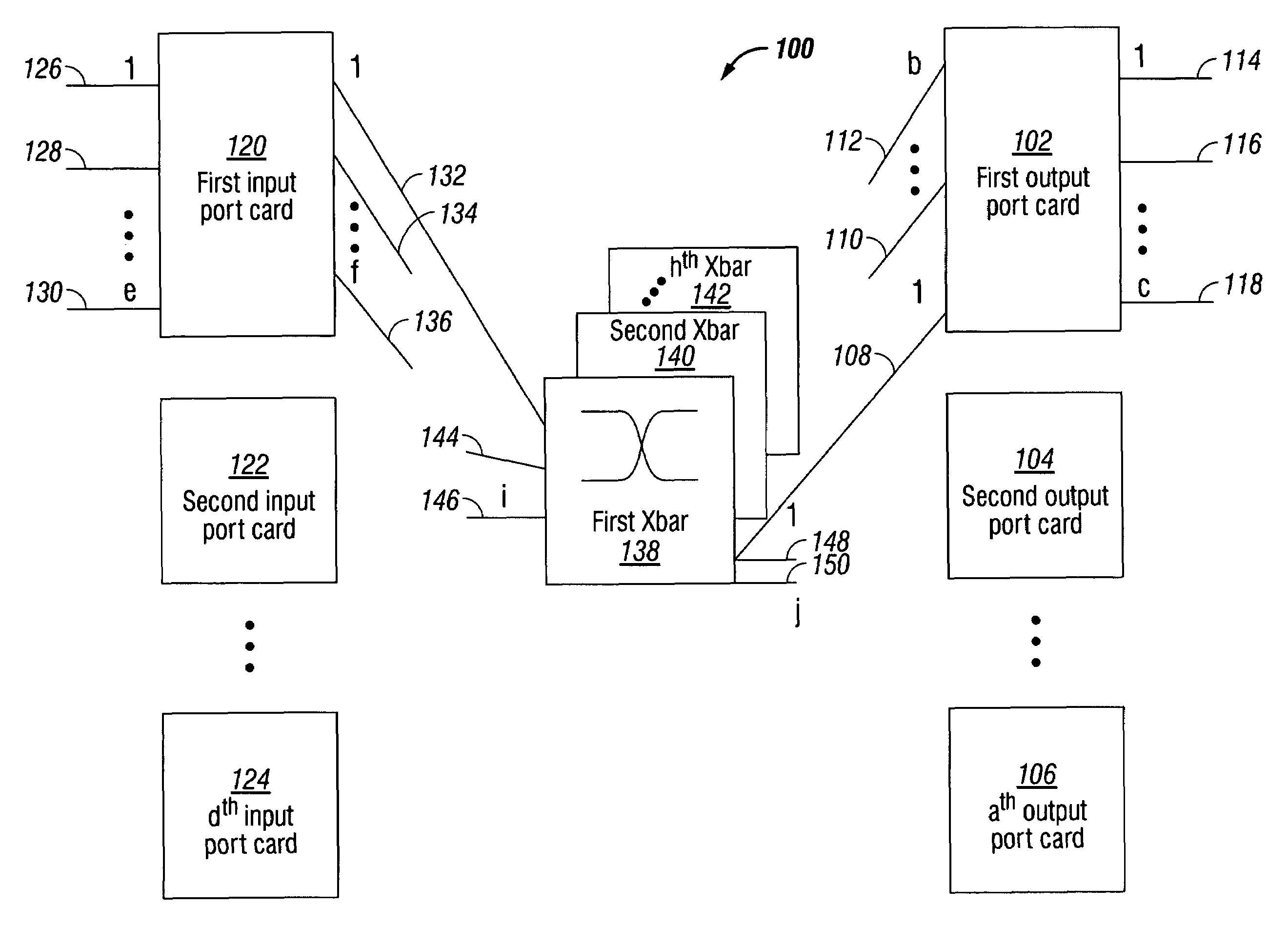
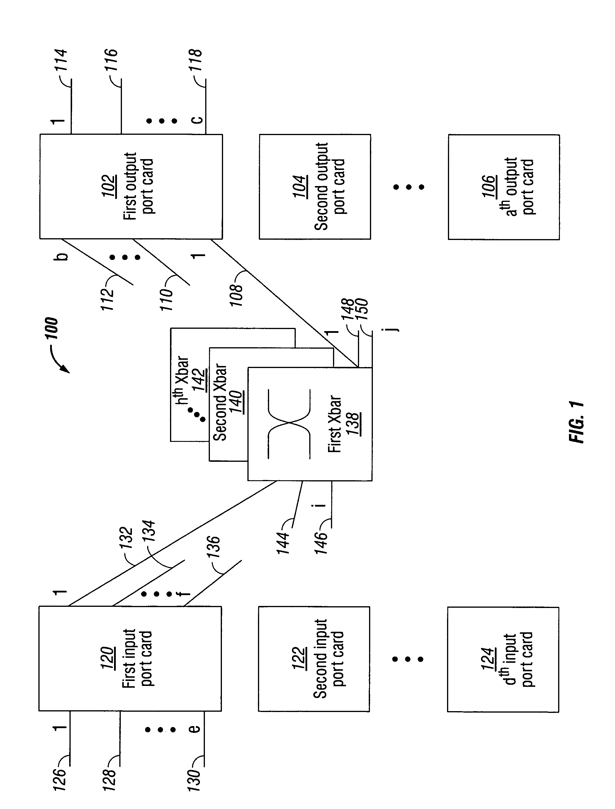
[0041]FIG. 1 is a schematic block diagram of the present invention system for cut-through packet routing in a packet communications switch fabric. The system 100 comprises an output port card including a plurality of egress ports. Shown are output port cards 1 through a (102, 104, 106, respectively), where the value of a is not limited to any particular value. Using the first output port card 102 as an example, a plurality of selectable backplane data links is shown. Backplane data links 1 through b are shown (108, 110, and 112, respectively), but the invention is not limited to any particular value of b. Egress ports 1 through c are shown (114, 116, and 118, respectively). Again, c is not limited to any particular value.

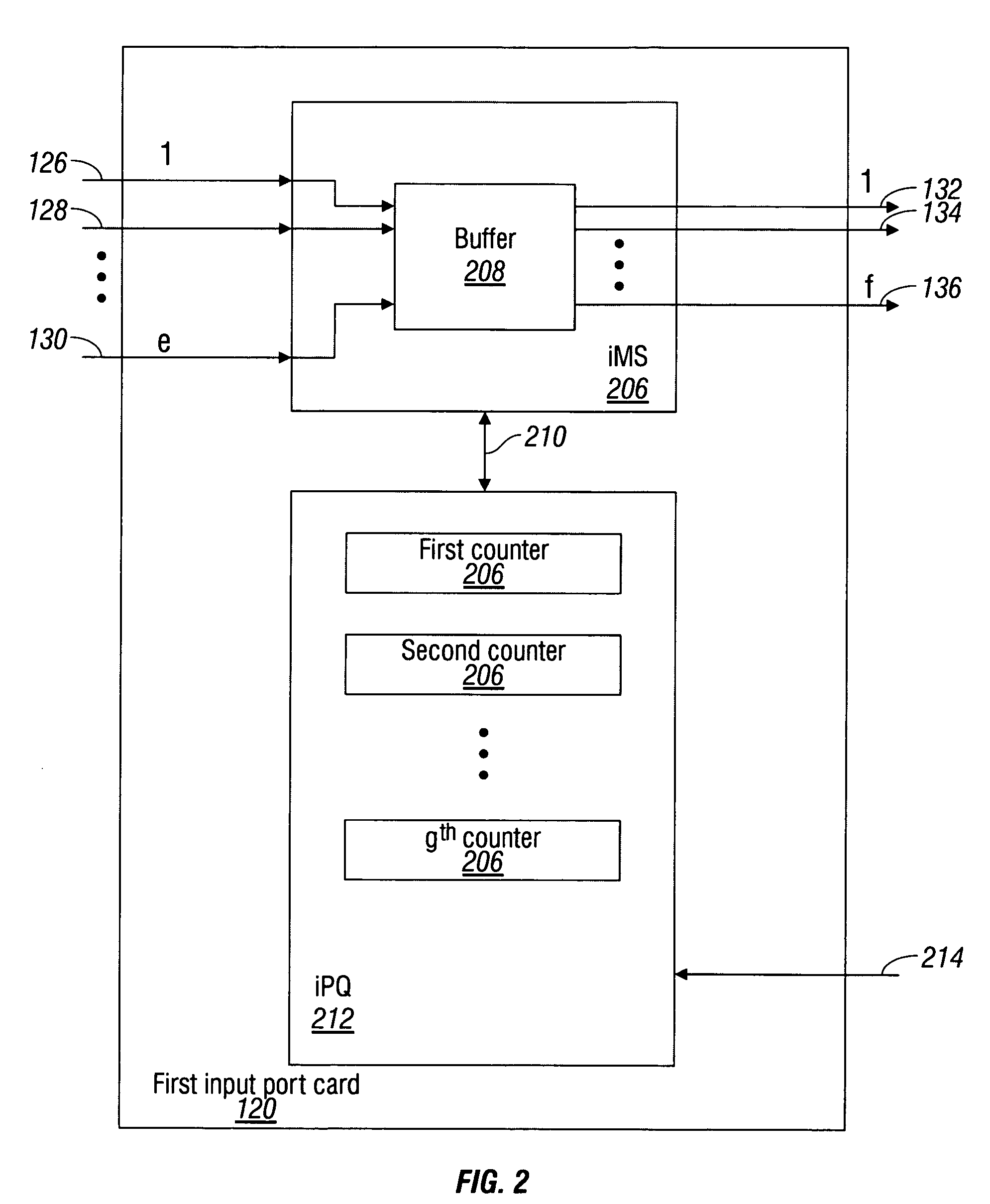
[0042]The system 100 also includes an input port card. Shown are input port cards 1 through d (120, 122, and 124, respectively), where the value of d is not limited to any particular value. Using first input port cards 120 as an example, a plurality of ingress ports...


PUM


Abstract

A system and method are provided for cut-through packet routing in a packet communications switch fabric. The method comprises: accepting information packets addressed to a plurality of output port card egress ports at an input port card ingress port; routing information packets between port cards on backplane data links through an intervening crossbar; maintaining a credit counter for each port card egress destination, at the input port card; decrementing the counter in response to transmitting cells in a packet from the input port card; and, incrementing the counter in response to transmitting cells from the packet at the output port card. In some aspects of the method, accepting information includes buffering the packets in an ingress memory subsystem (iMS). Routing information includes the iMS transmitting buffered packets on a selected backplane data link. Decrementing the counter includes the iMS communicating with the iPQ in response to transmitting a cell.

Description

RELATED APPLICATIONS[0001]This application is a continuation-in-part of a application entitled, SYSTEM AND METHOD FOR SWITCHING VARIABLY SIZED INFORMATION GROUPS, invented by Yun et al., Ser. No. 10 / 023,266, filed Dec. 14, 2001 now abandoned.[0002]This application is a continuation-in-part of a application entitled, SYSTEM AND METHOD FOR SIMULTANEOUS DEFICIT ROUND ROBIN PRIORITIZATION, invented by Yun et al., Ser. No. 10 / 022,673, filed Dec. 17, 2001 now U.S. Pat. No. 7,079,545.[0003]This application is a continuation-in-part of a pending application entitled, SYSTEM AND METHOD FOR GRANTING ARBITRATED BIDS IN THE SWITCHING OF INFORMATION, invented by Yun et al., Ser. No. 10 / 029,581, filed Dec. 20, 2001.[0004]This application is a continuation-in-part of a application entitled, SYSTEM AND METHOD FOR HIERARCHICAL SWITCHING, invented by Yun et al., Ser. No. 10 / 035,835, filed Dec. 24, 2001 now U.S. Pat. No. 7,020,131.[0005]This application is a continuation-in-part of a pending applicati...

Claims


Application Information

Patent Timeline
Patent Type & Authority Patents(United States)
IPC IPC(8): H04Q11/00
CPCH04L12/5601H04L49/106H04L2012/5665H04L2012/5675
Inventor HUBER, JOHN DAVIDMILLER, KIRK ALVINHELLMER, MICHAEL JOHNYUN, KENNETH YIJAMES, KEVIN WARRENBENDAK, GEORGE BESHARA
Owner QUALCOMM INC
Why Eureka
Try Eureka