Manifold valve and pressure transducer assembly

a technology of pressure transducer and manifold valve, which is applied in the direction of drawing-off water installation, container discharging method, instruments, etc., can solve the problems of high cost of these types of transmitters, high cost of these transmitters, and high cost of these units

Inactive Publication Date: 2007-06-19
NOSHOK
View PDF18 Cites 24 Cited by
  • Summary
  • Abstract
  • Description
  • Claims
  • Application Information

AI Technical Summary

Benefits of technology

[0008]The present invention provides a novel means for monitoring the pressure in a fluid pipeline. The pressure indicating assembly uses a manifold valve assembly and a pressure transducer assembly comprising two pressure transducers. These components are attached in a unique way so as to allow accessibility and interchangeability with commercially available transducers and manifold valve assemblies. The invention improves on known assembly and mounting means between the pressure transducers and the manifold valve.

Problems solved by technology

The costs of these types of transmitters typically are higher than the cost of the manifold valve.
The time required to assemble these units into fluid pipelines is significantly lower than assembling separate manifold and pressure transducers, but the costs of these units also are higher.
The costs of the individual components are relatively low, but the costs associated with assembling them into fluid pipelines are significantly higher than integrated units.
This assembly, however, still makes use of piping components, and although the manifold valve is modular, the pressure transducers are not.

Method used


Image

  • Manifold valve and pressure transducer assembly
  • Manifold valve and pressure transducer assembly
  • Manifold valve and pressure transducer assembly

Examples


Embodiment Construction

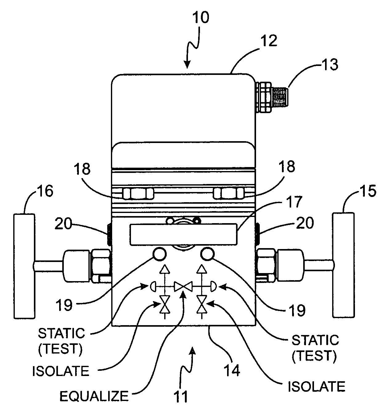
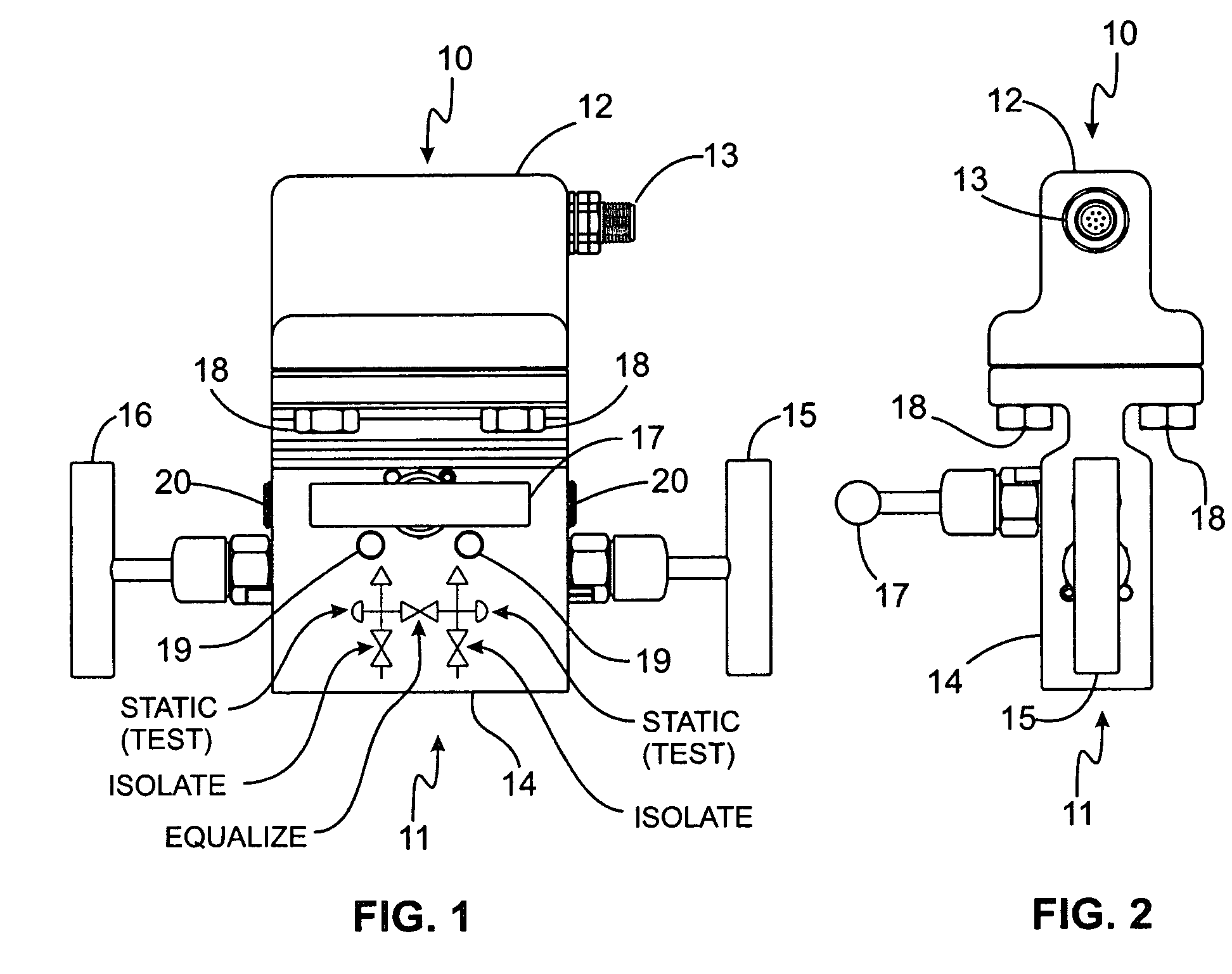
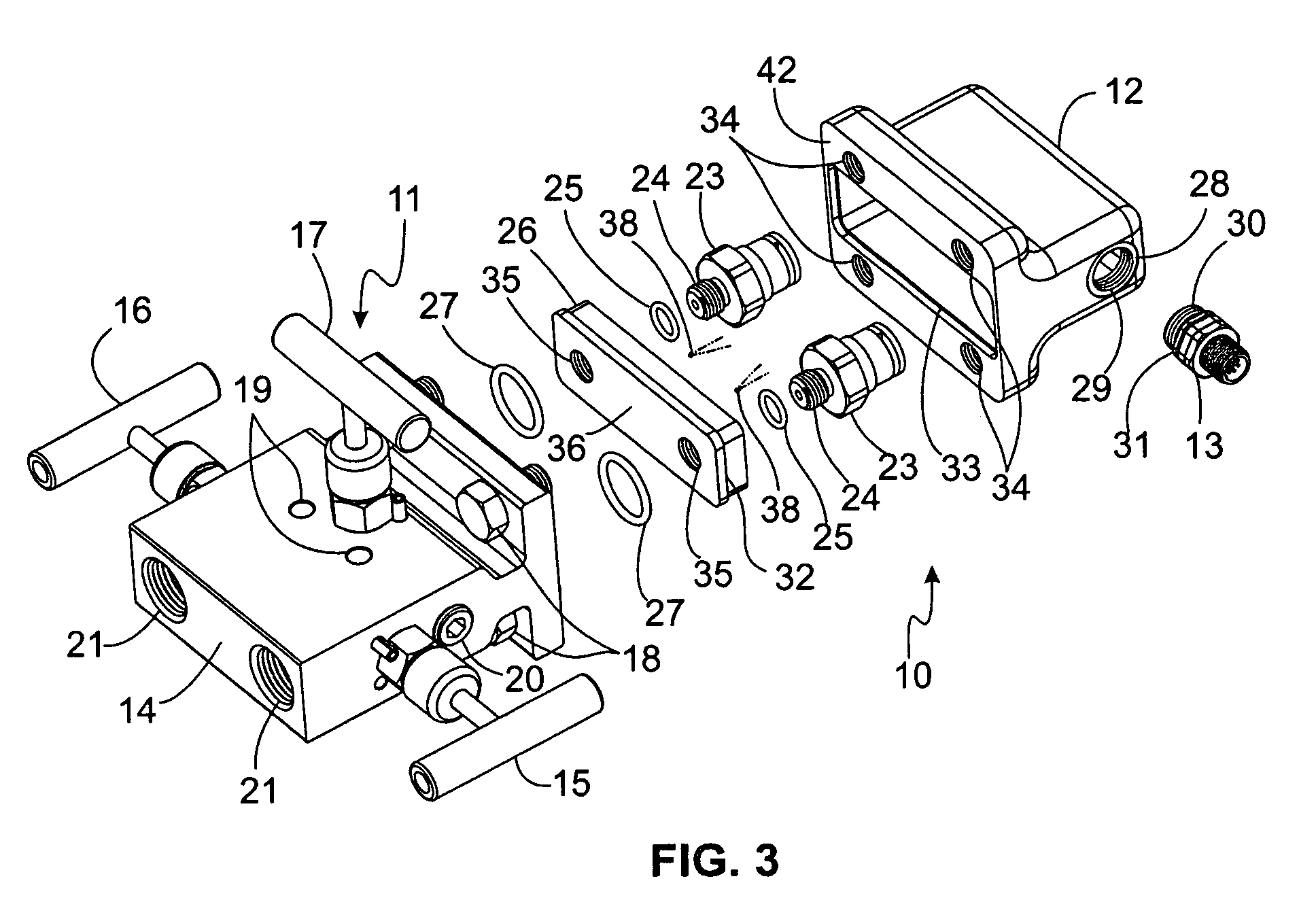
[0023]A preferred embodiment is shown in FIG. 1 of an improved manifold valve and pressure transducer assembly consisting of a manifold assembly 11 detachably mounted with four bolts 18 to a pressure transducer assembly 10. Two of said bolts 18 are shown in FIGS. 1 and 2, and all four bolts 18 are shown in FIG. 4. Attached to the manifold valve body 14 are two isolation valves 15 and 16 that are used to open and close two segregated fluid passageways between two inlet ports 21 of FIG. 3 and two outlet ports 22 of FIG. 4. The inlet ports 21 are shown as threaded connections but can be any convenient attachment to a fluid pipeline. When mounted to additional manifold valves, the inlet ports 21 can be a flange type similar to the flange connection on the two outlet ports 22 of the manifold body 14. The flange connection has been adopted by the Manufacturers Standardization Society of the Valve and Fitting Industry (MSS) SP-99 as a standard and is considered a direct mounting connection...


PUM


Abstract

An assembly for measuring differential pressures includes a manifold valve and pressure transducer assembly including two pressure transducers. The manifold valve includes two pressure inlet ports and two pressure outlet ports that communicate through the manifold's isolation valves. An equalization valve connects the two pressure lines. Mating flanges on the manifold valve and pressure transducer assembly are bolted together to form a pressure tight seal between the manifold valve outlet ports and the pressure transducer assembly inlet ports. The pressure transducer assembly also includes a mounting plate for supporting the pressure transducers. The transducers generate an electrical signal corresponding to inlet pressure. Signals from pressure transducers and an optional thermistor for each are wired to an electrical connector mounted on the side of the assembly. The signals are electronically compared with an external signal processing circuit that outputs a representative signal of the differential pressure.

Description

BACKGROUND OF THE INVENTION[0001]The present invention relates to manifold valves and pressure transducers in fluid communication with main fluid pressure lines, and more particularly to assemblies of manifold valves and pressure transducers for outputting signals representing pressures in two pressurized fluid lines.[0002]Manifold valves are known in the art. Manifold valves typically are mounted between the main fluid pressure lines and the pressure transducers. Manifold valves permit isolating the pressure lines from the pressure transducers in order to facilitate their removal or replacement and are required for calibration purposes. The manifold valve of the present invention includes a first inlet port and a second inlet port with internal passageways that run past isolation valves to a first outlet port and second outlet port that are connected to corresponding inlet ports on the pressure transducers.[0003]Differential pressure transmitters are known in the art. Manifold valv...

Claims


Application Information

Patent Timeline
Patent Type & Authority Patents(United States)
IPC IPC(8): G05D16/00
CPCG01L19/0015Y10T137/0447
Inventor LANCASTER, MICHAEL F.
Owner NOSHOK
Why Eureka
Try Eureka