
Environmental continuous air monitor inlet with combined preseparator and virtual impactor

a technology of environmental continuous air and monitor, which is applied in the direction of auxillary pretreatment, instruments, separation processes, etc., can solve the problems of rapid filter clogging, premature shutdown, and rapid clogging

Inactive Publication Date: 2007-06-19
LOS ALAMOS NATIONAL SECURITY
View PDF9 Cites 16 Cited by
  • Summary
  • Abstract
  • Description
  • Claims
  • Application Information

AI Technical Summary

Problems solved by technology

However, a problem with current environmental continuous air monitor designs is that sampled ambient air may contain large quantities of fine particles (particles in the size range less than about 2.5 micrometers aerodynamic diameter) and smoke particles (particle diameters of between about 0.1-1.0 micrometers), which can cause rapid filter clogging and subsequent premature shutdown.
It has long been recognized that fine and smoke sized particles cause rapid clogging of the pore structures and, understandably, sampling at high volumetric rates accelerates dust loading of the sample filter and, where smoke or fine dusts are involved, filter clogging and sampling failure.
This frequent shutdown and need for replacement of filters, is time consuming and expensive, and necessarily can interrupt an important monitoring and consequence management process.
Elsewhere, energetic disturbances of soil that can accompany earth moving and construction activities can create high dust loads containing a large fraction of fines, and smoke particles are copiously generated by internal combustion engines, especially diesel engines.
These conditions can quickly cause a prior art environmental continuous air monitor rapidly to experience clogged filters and a subsequent shut down of operation.

Method used


Image

  • Environmental continuous air monitor inlet with combined preseparator and virtual impactor
  • Environmental continuous air monitor inlet with combined preseparator and virtual impactor
  • Environmental continuous air monitor inlet with combined preseparator and virtual impactor

Examples


Embodiment Construction

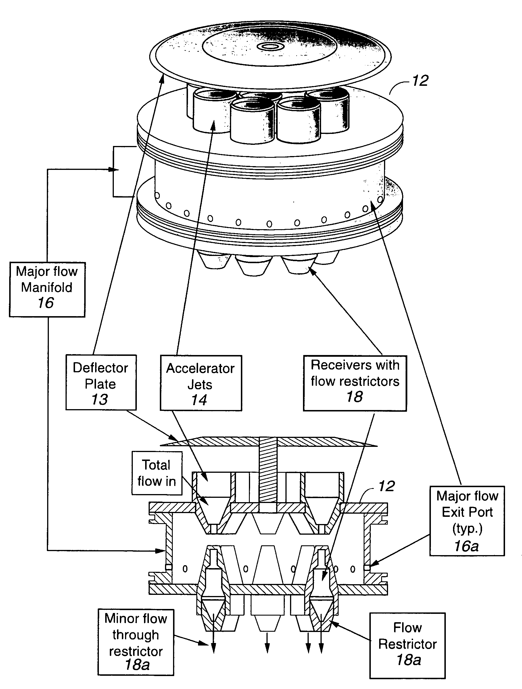
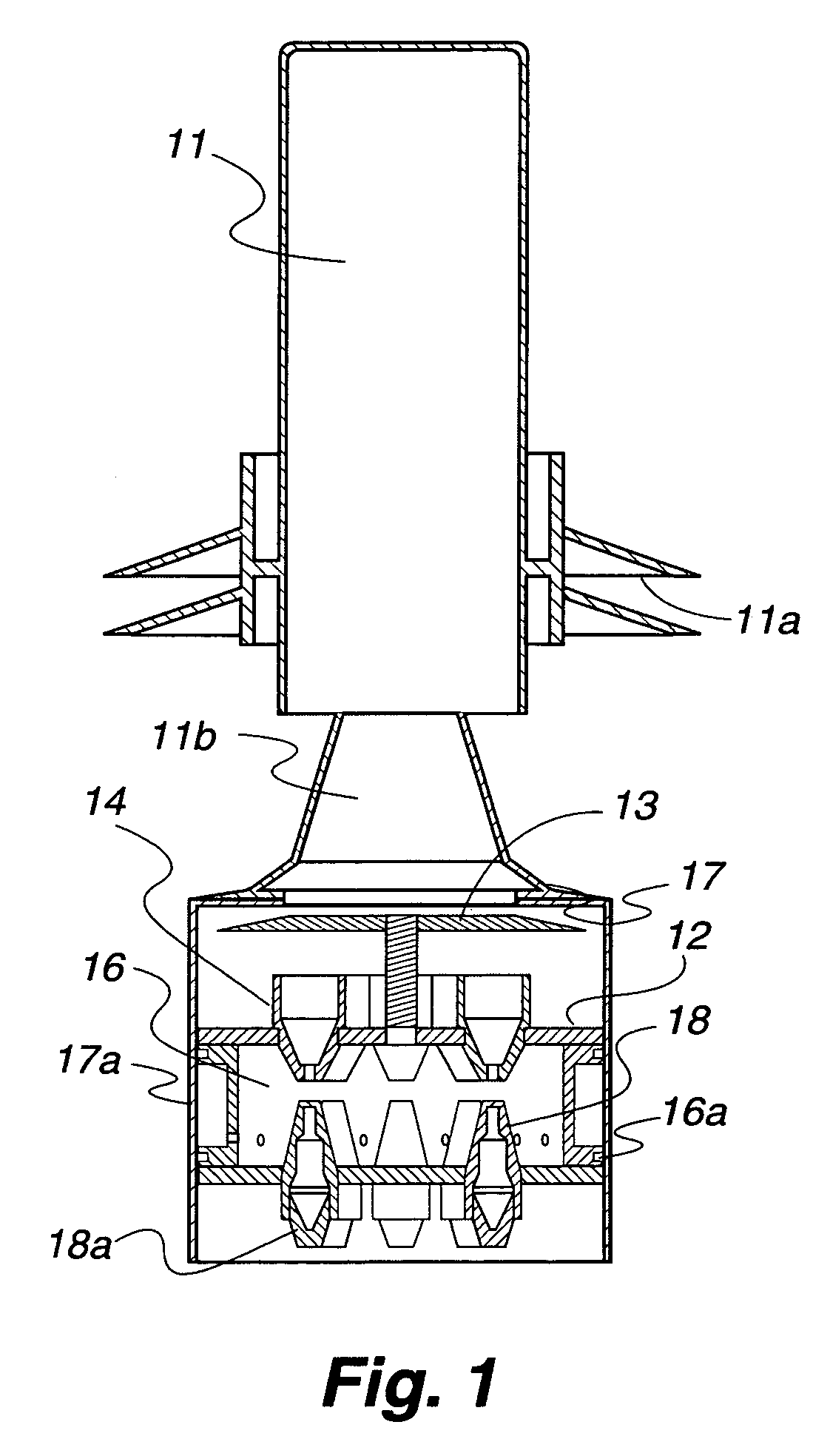
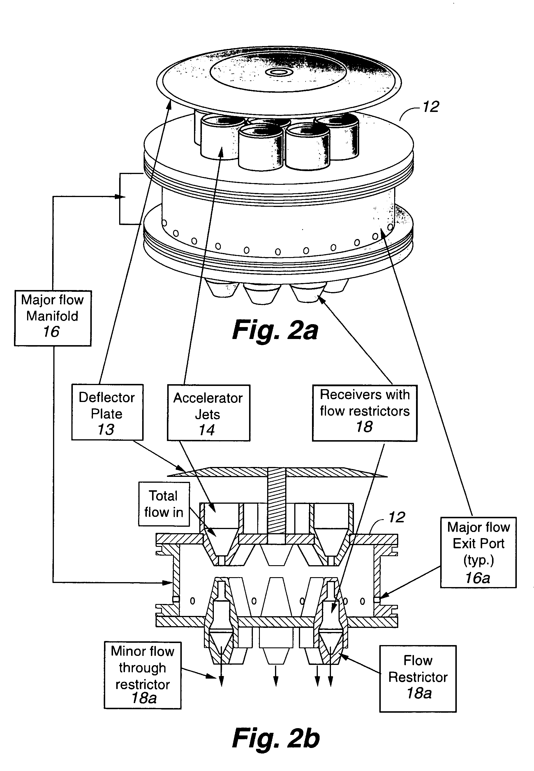
[0013]The present invention provides apparatus that is positioned in the airflow path of a high volume environmental continuous air monitor ahead of the sample collection stage to remove potentially interfering and clogging particles in the collected air. The invention may be understood most easily through reference to the drawings.

[0014]Referring first to FIG. 1, a cross-sectional view of one embodiment of the present invention is shown. Pre-separator 11 may be any of numerous acceptable pre-separators, but in FIG. 1 a cyclo-shroud type pre-separator (U.S. Pat. No. 6,530,287) is shown. The requirements of pre-separator 11 are that it buffer the inlet of a continuous air monitor against the sometime high velocity, dust-laden ambient air input through inlets 11a. The resultant inertial and drag effects on pieces of airborne debris or insects that are carried into the inlet and then subjected to strong cyclonic or centrifugal forces, causes such debris to be removed and trapped before...


PUM

PropertyMeasurementUnit
aerodynamic diameteraaaaaaaaaa
sizesaaaaaaaaaa
aerodynamic diameteraaaaaaaaaa

Abstract

An inlet for an environmental air monitor is described wherein a pre-separator interfaces with ambient environment air and removes debris and insects commonly associated with high wind outdoors and a deflector plate in communication with incoming air from the pre-separator stage, that directs the air radially and downward uniformly into a plurality of accelerator jets located in a manifold of a virtual impactor, the manifold being cylindrical and having a top, a base, and a wall, with the plurality of accelerator jets being located in the top of the manifold and receiving the directed air and accelerating directed air, thereby creating jets of air penetrating into the manifold, where a major flow is deflected to the walls of the manifold and extracted through ports in the walls. A plurality of receiver nozzles are located in the base of the manifold coaxial with the accelerator jets, and a plurality of matching flow restrictor elements are located in the plurality of receiver nozzles for balancing and equalizing the total minor flow among all the plurality of receiver nozzles, through which a lower, fractional flow extracts large particle constituents of the air for collection on a sample filter after passing through the plurality of receiver nozzles and the plurality of matching flow restrictor elements.

Description

[0001]The present invention generally relates to environmental continuous air monitors, and, more specifically relates to environmental air monitor inlets used in adverse environmental conditions. This invention was made with Government support under Contract No. W-7405-ENG-36 awarded by the U.S. Department of Energy. The Government has certain rights in the invention.BACKGROUND OF THE INVENTION[0002]Environmental continuous air monitors (ECAMs) are becoming much more important to National defense programs in light of recent world events. The specter of the use of “dirty” nuclear devices or radiological dispersal devices (RDDs) by terrorists has become a real possibility. To handle the consequences of such attacks, high volume environmental continuous air monitors must be reliable, and provide service over long periods of time without requiring frequent maintenance. However, a problem with current environmental continuous air monitor designs is that sampled ambient air may contain l...

Claims


Application Information

Patent Timeline
Patent Type & Authority Patents(United States)
IPC IPC(8): B01D45/00
CPCB01D45/12Y10S55/14
Inventor RODGERS, JOHN C.
Owner LOS ALAMOS NATIONAL SECURITY
Learn More