Laser wavefront characterization

Active Publication Date: 2007-06-19
KESTREL CORP
View PDF2 Cites 31 Cited by
  • Summary
  • Abstract
  • Description
  • Claims
  • Application Information

AI Technical Summary

Benefits of technology

[0014]It is still another object of the present invention to provide for an infrared laser wavefront sensor that is not sensitive to increased background noise from thermal heating of the optical elements.

Problems solved by technology

Many applications impose unique restrictions that limit the application of conventional laser diagnostics.
Size, weight, robustness, and unattended operations all make conventional measurement sensors difficult to adapt.

Method used


Image

  • Laser wavefront characterization
  • Laser wavefront characterization
  • Laser wavefront characterization

Examples


Embodiment Construction

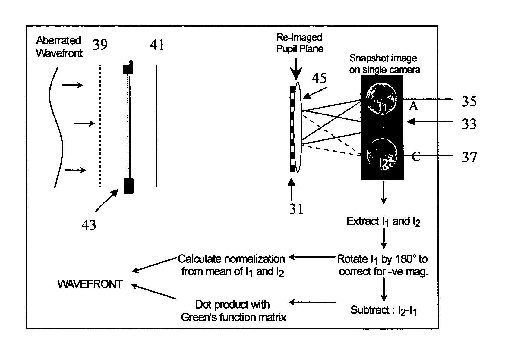
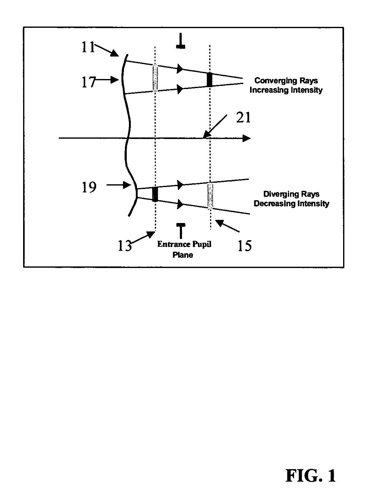
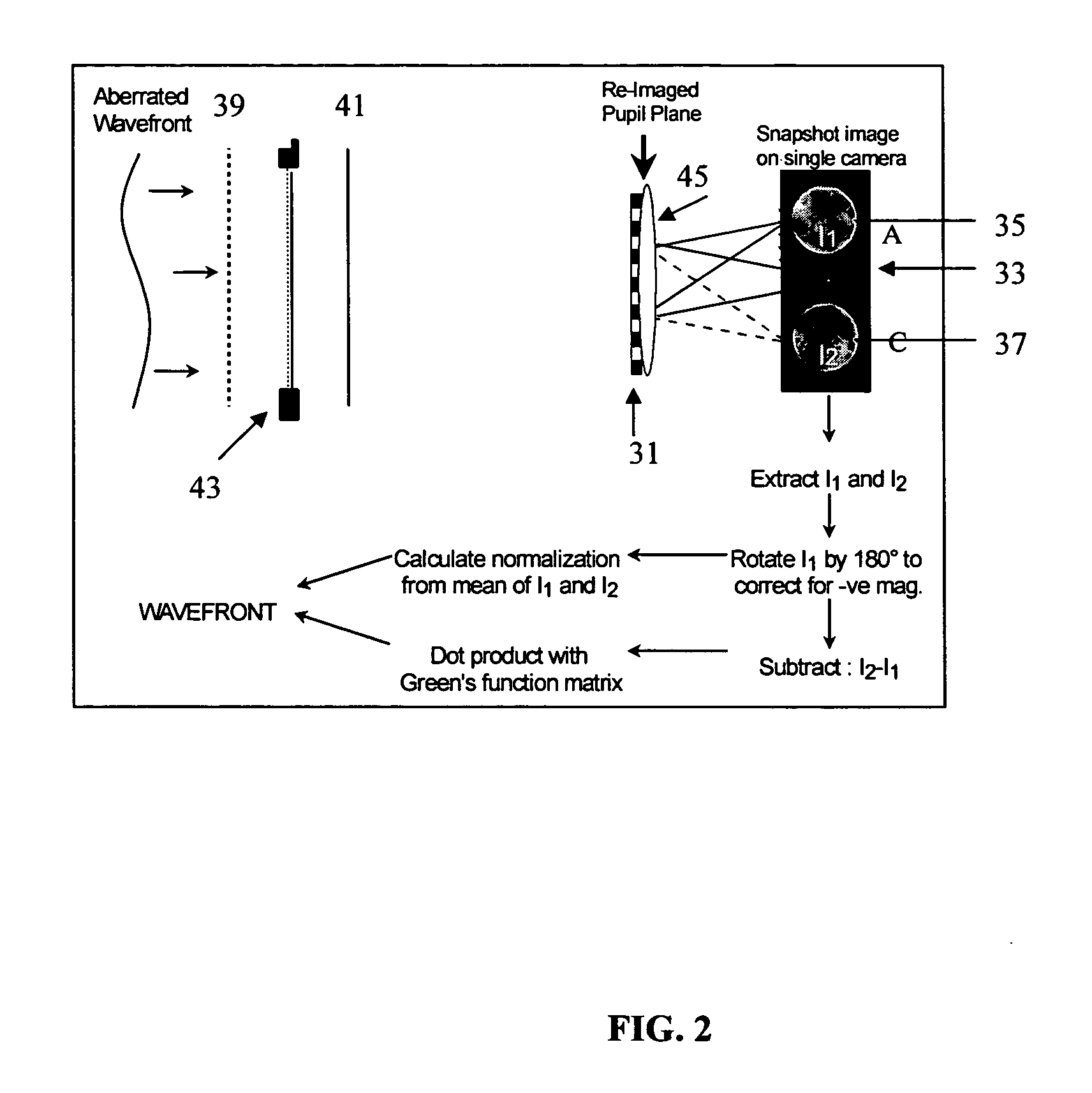
[0048]The use of a distorted grating wavefront sensing for determining the characteristics of a laser is described below. With reference to FIG. 1, in order for such a wavefront sensor to work the difference between the intensities of the wavefront with a known aberration 11 at a first image plane 13 and a second image plane 15 is taken. This difference in the intensities indicates the position, direction, and magnitude of the aberration to be corrected. The shape of the wavefront is computed from the difference matrix through a matrix multiplication with a pre-computed Green's function. It is therefore critical that the multiple frames are accurately and consistently registered, the detector is well characterized and the introduced aberration is a controlled function. Preferably, the wavefront sensor would record the multiple images on a single detector.

[0049]FIG. 1 illustrates the basics for the wavefront curvature technique by considering the propagation of a wavefront 11 between...


PUM


Abstract

The device and method of the present invention are useful for determining the characteristics of an infrared wavefront. The present invention involves positioning a beam of light containing the infrared wavefront to be characterized onto a distorted grating, using the grating to produce a plurality of images, determining the infrared wavefront from the plurality of images and analyzing the infrared wavefront for features that characterize the infrared wavefront.

Description

CLAIM FOR PRIORITY[0001]A claim for priority is made in this application for the provisional application No. 60 / 491,076 filed on Jul. 30, 2003.GOVERNMENTAL RIGHTS CLAUSE[0002]This invention is made with U.S. Government support under Contract F29601-02-C-0130 awarded by the U.S. Air Force. The U.S. Government has certain rights in the invention.FIELD OF THE INVENTION[0003]This invention relates to a distorted grating based wavefront sensor (DGWFS) developed to measure wavefronts of infrared radiation. The invention has been shown to produce accurate wavefront data while simultaneously producing accurate tip-tilt data along with the higher order terms in a very rugged configuration.BACKGROUND OF THE INVENTION[0004]With infrared lasers now being developed for a wide range of applications there is a need for diagnostics instrumentation for characterizing performance and to serve as the input to a dynamic active beam brightness correction system. Many applications impose unique restricti...

Claims


Application Information

Patent Timeline
IPC IPC(8): G01J5/00
CPCG01J9/00
Inventor OTTEN, III, LEONARD JOHNHARRISON, PAULCUEVAS, DESIRAE L.FOURNIER, PAUL
Owner KESTREL CORP
Why Eureka
Try Eureka