

Dichromatic curved reflector structure for improving signal-to-noise ratio of fluorescence detector
A technology of fluorescence detector and mirror, which is applied in the direction of fluorescence/phosphorescence, instruments, measuring devices, etc., can solve the problem of rarely reflecting excitation light, so as to prevent the increase of background noise and improve the detection signal-to-noise ratio
- Summary
- Abstract
- Description
- Claims
- Application Information
AI Technical Summary
Problems solved by technology
Method used
Image

Examples
Embodiment 1
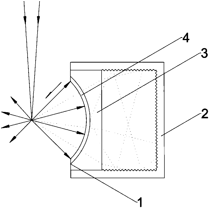
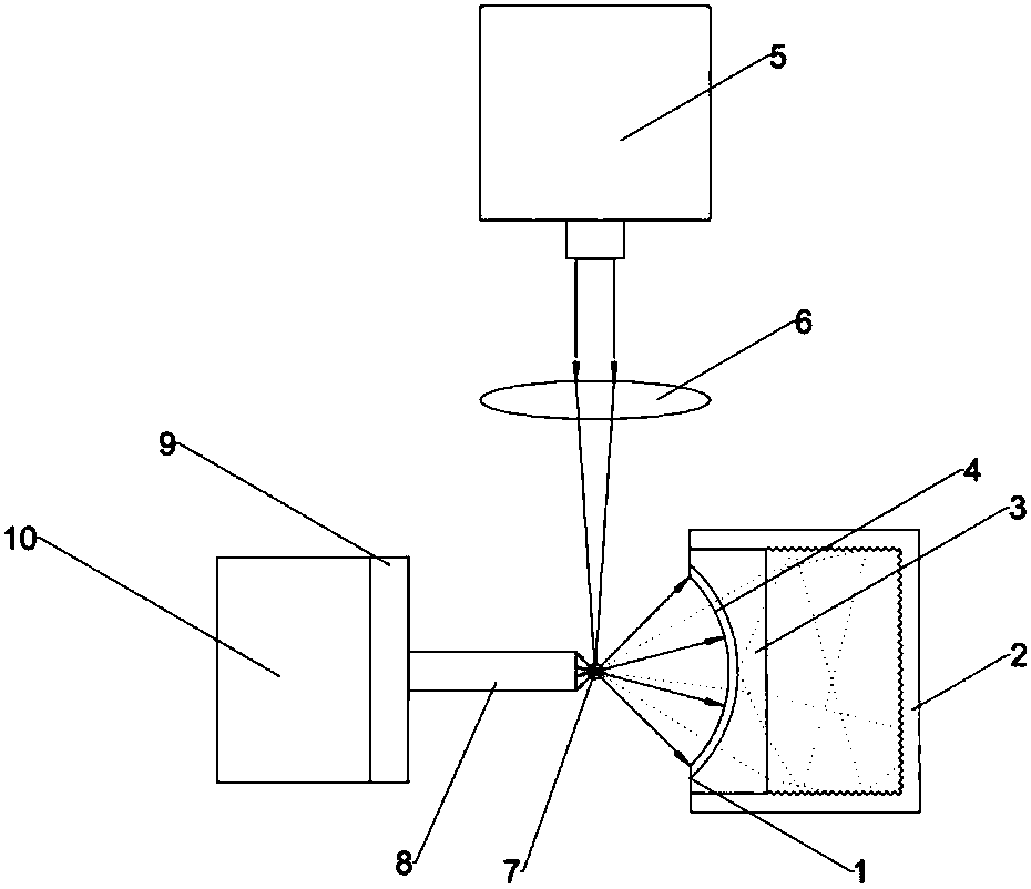
[0029] The optical system is self-built, and the dichromatic curved mirror structure is set in the laser-induced fluorescence orthogonal detection system. System structure such as figure 2 As shown, it includes a dichroic curved mirror 1 (curved concave lens 3, dichroic film 4), light absorption box 2, laser 5, convex lens 6, capillary 7, optical fiber 8, optical filter 9, and detector 10. The curved surface of the dichroic curved mirror 1 is a spherical surface, the center of which is coincident with the axis of the capillary 7 and the excitation point of the laser, and its concave surface faces the direction of the detector 10 . During operation, after the excitation light is emitted from the laser 5, it is focused on the capillary 7 through the convex lens 6. The excitation point on the capillary radiates mixed light to the surroundings simultaneously, including sample fluorescence and laser stray light, wherein the mixed light that deviates from the detection direction s...
Embodiment 2
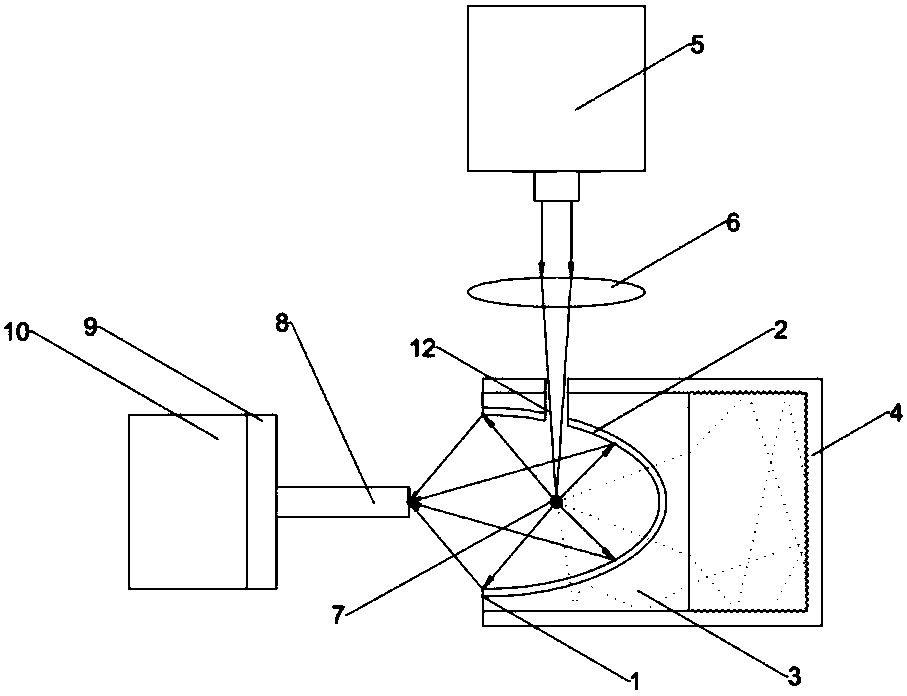
[0033] The optical system is self-built, and the dichromatic curved mirror structure is set in the laser-induced fluorescence orthogonal detection system. System structure such as image 3As shown, it includes a dichroic curved mirror 1 (curved concave lens 3, dichroic film 4), light absorption box 2, laser 5, convex lens 6, capillary 7, optical fiber 8, filter 9, detector 10, through hole 12 . The curved surface of the dichroic curved mirror 1 is an ellipsoid, and its near mirror focus coincides with the axis of the capillary 7 and the laser excitation point, its concave surface faces the direction of the detector 10, and its far mirror focus coincides with the optical fiber 8 port. During operation, after the laser light is emitted from the laser 5 , it is focused by the convex lens 6 and irradiated on the capillary 7 through the through hole 12 . The excitation point on the capillary radiates mixed light to the surroundings simultaneously, including sample fluorescence an...
Embodiment 3
[0037] Self-built optical system, the dichroic curved mirror structure is set in the laser-induced fluorescence orthogonal detection system, the structure is as follows Figure 4 As shown, it includes a dichroic curved mirror 1 (curved concave lens 3, dichroic film 4), light absorption box 2, laser 5, convex lens 6, capillary 7, filter 9, detector 10, through hole 12, lens 14 . Among them, the curved surface of the dichroic curved mirror 1 is a paraboloid, its focal point coincides with the axis of the capillary 7 and the laser excitation point, and its concave surface faces the direction of the detector 10 . When the system is working, the laser is emitted from the laser 5, focused by the convex lens 6, and irradiated on the capillary 7 through the through hole 12. The excitation point on the capillary radiates mixed light to the surroundings simultaneously, including sample fluorescence and laser stray light, wherein the mixed light that deviates from the detection directio...
PUM
| Property | Measurement | Unit |
|---|---|---|
| Outer diameter | aaaaa | aaaaa |
| The inside diameter of | aaaaa | aaaaa |
| Outer diameter | aaaaa | aaaaa |
Abstract
Description
Claims
Application Information