Radio frequency identification device with visual indicator

a radio frequency identification and visual indicator technology, applied in the direction of identification means, burglar alarm mechanical actuation, instruments, etc., can solve the problems of privacy concerns, difficult spatial discrimination in reading and detection of devices,

Active Publication Date: 2007-06-19
AVERY DENNISON CORP
View PDF32 Cites 116 Cited by
  • Summary
  • Abstract
  • Description
  • Claims
  • Application Information

AI Technical Summary

Problems solved by technology

Thus detection of devices is accomplished over a significantly-sized region, and spatial discrimination in reading and detection of devices may be difficult.
One concern that has been raised regarding RFID devices is that their ability to be read over relatively long distances may implicate privacy concerns for people having objects with RFID devices attached thereto or otherwise coupled thereto.

Method used


Image

  • Radio frequency identification device with visual indicator
  • Radio frequency identification device with visual indicator
  • Radio frequency identification device with visual indicator

Examples


Embodiment Construction

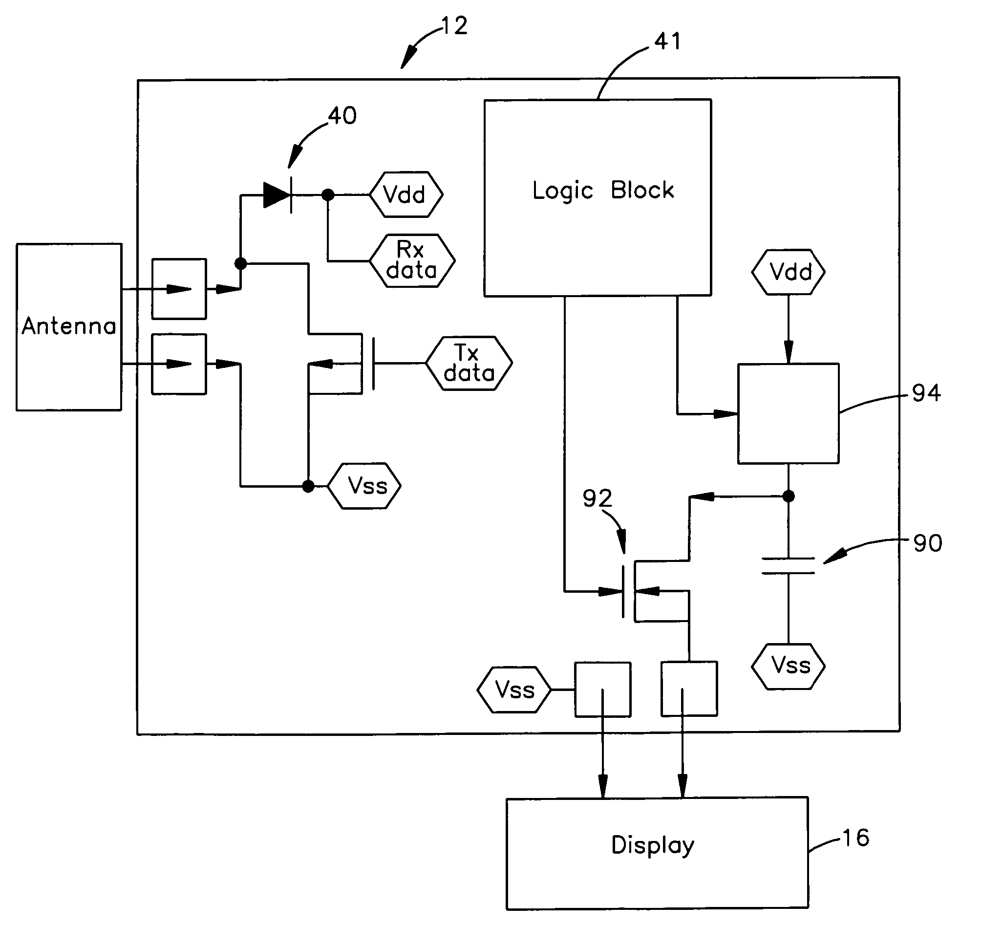
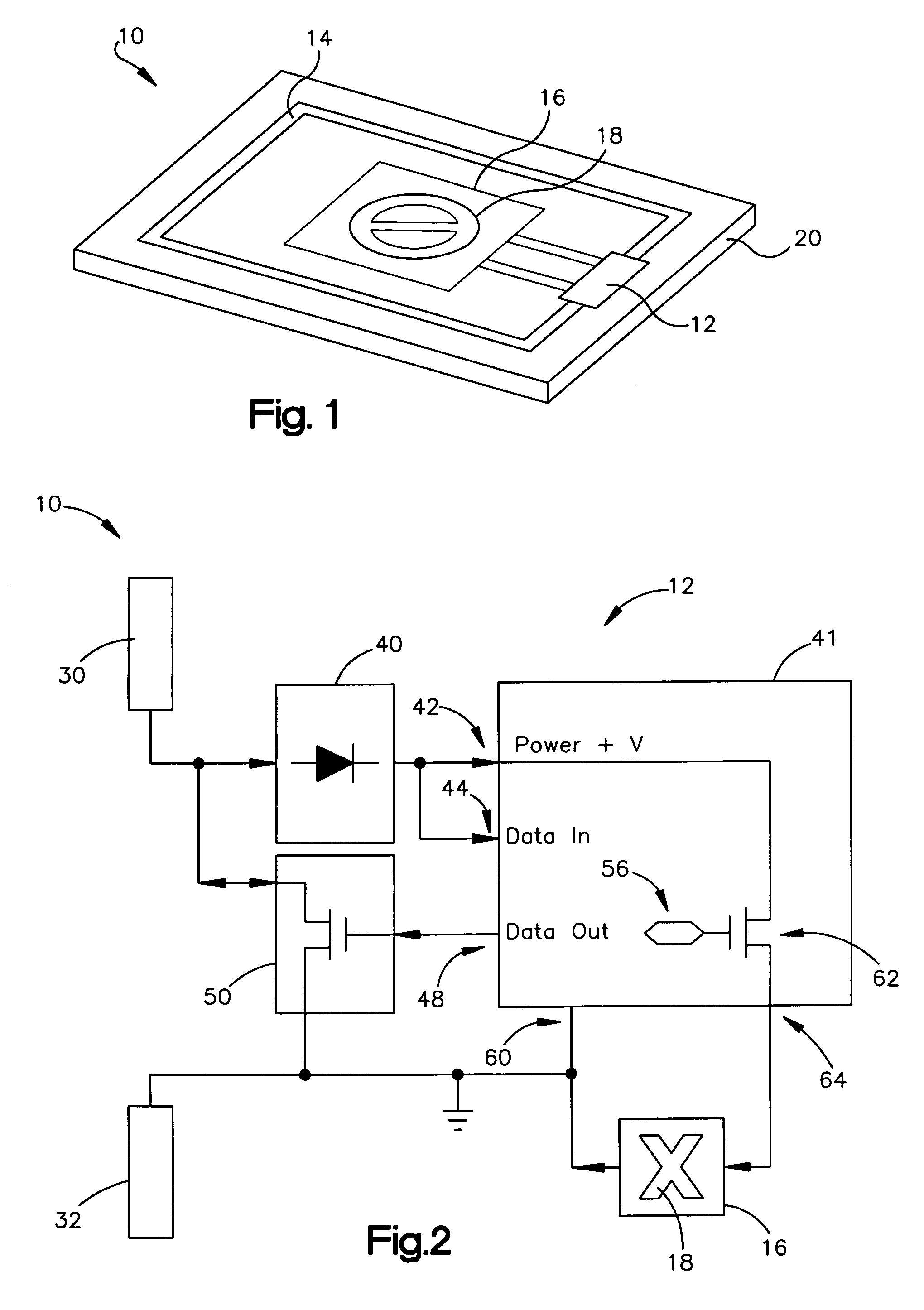
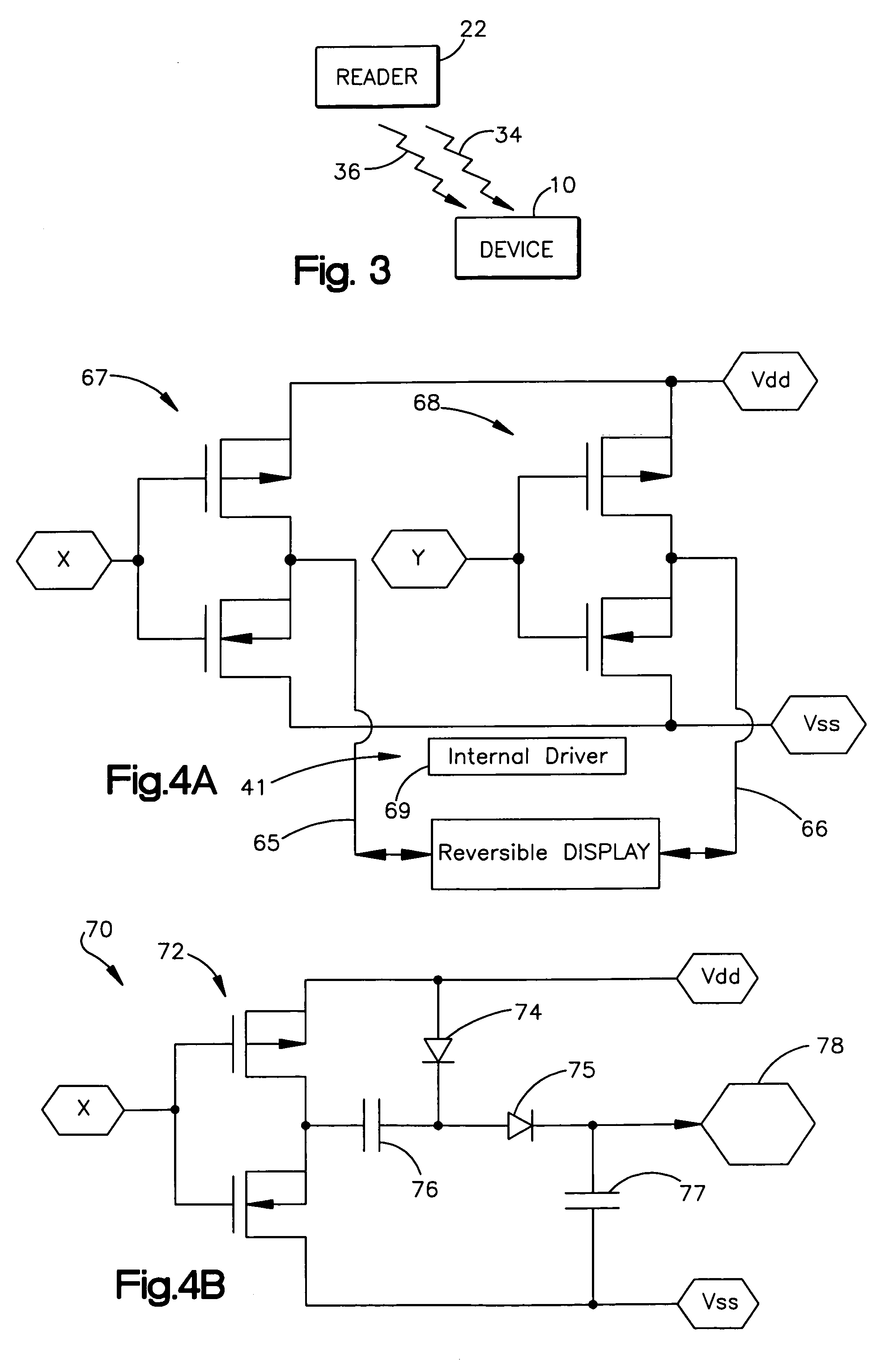
[0032]An RFID device includes a chip, an antenna operatively coupled to the chip, and a visual indicator operatively coupled to the chip. The visual indicator provides a visual indication of an operative state of the device. The visual indication may be human readable and / or machine readable, and may provide visual indication that is dependent on a change in an operative state of the device. The operative state that triggers the visual indication may include a state in which the chip has temporarily or permanently been rendered inoperative or disabled, that is, in which the chip no longer responds to, or otherwise interacts with, ordinary incoming RF signals such as from a device reader. The visual indicator may be included in a display that functions by any of a variety of suitable mechanisms, such as by use of electrochromic materials, thermochromic materials, liquid crystals, or chemically-reactive materials. The visual indication may include any of a wide variety of human-readab...


PUM


Abstract

An RFID device includes a chip, an antenna operatively coupled to the chip, and a visual indicator operatively coupled to the chip. The visual indicator provides a visual indication of an operative state of the device. The visual indication may be human readable and / or machine readable, and may provide visual indication that is dependent on a change in an operative state of the device. The operative state that triggers the visual indication may include a state in which the chip has temporarily or permanently been rendered inoperative or disabled, that is, in which the chip no longer responds to, or otherwise interacts with, ordinary incoming RF signals such as from a device reader. The visual indicator may be included in a display that functions by any of a variety of suitable mechanisms, such as by use of electrochromic materials, thermochromic materials, liquid crystals, or chemically-reactive materials.

Description

BACKGROUND OF THE INVENTION[0001]1. Technical Field of the Invention[0002]The invention relates to radio frequency identification (RFID) devices.[0003]2. Description of the Related Art[0004]Radio frequency identification (RFID) tags and labels (collectively referred to herein as “devices”) are widely used to associate an object with an identification code. RFID devices generally have a combination of antennas and analog and / or digital electronics, which may include for example communications electronics, data memory, and control logic. For example, RFID tags are used in conjunction with security-locks in cars, for access control to buildings, and for tracking inventory and parcels. Some examples of RFID tags and labels appear in U.S. Pat. Nos. 6,107,920, 6,206,292, and 6,262,692, all of which are hereby incorporated by reference in their entireties.[0005]As noted above, RFID devices are generally categorized as labels or tags. RFID labels are RFID devices that are adhesively or othe...

Claims


Application Information

Patent Timeline
Patent Type & Authority Patents(United States)
IPC IPC(8): G08B13/14
CPCG06K19/0723G06K19/073G06K19/07703G09F3/0335G09F3/0341
Inventor FORSTER, IAN J.
Owner AVERY DENNISON CORP
Why Eureka
Try Eureka