
Systems and methods for capturing screen displays from a host computing system for display at a remote terminal

a computing system and display technology, applied in static indicating devices, data switching networks, instruments, etc., can solve the problems of service of a particular computing system or server, not being able to provide maintenance information to the user of the computing system over the telephone, and being unable to meet the needs of users, so as to reduce the amount of data, reduce the effect of terminal emulation on network bandwidth and reducing the amount of data

Inactive Publication Date: 2007-06-19
AMERICAN MEGATRENDS
View PDF47 Cites 46 Cited by
  • Summary
  • Abstract
  • Description
  • Claims
  • Application Information

AI Technical Summary

Benefits of technology

"The present invention provides systems and methods for terminal emulation that reduce the amount of data transmitted to the maintenance computing system, minimizing the impact on network bandwidth. This is achieved by using a hardware-based system that alleviates the need for software on the host computing system. The systems and methods use a video controller that outputs both digital and analog signal representations of the data to be displayed by the display terminal associated with the host computing system. The video controller uses a USB interface connected to the host computing system's USB port, which allows for emulation of a keyboard, mouse, and storage device. The systems and methods also include a frame grabber that captures the digital display data and comparators for comparing successive data sets. Overall, the present invention reduces the amount of data transmitted, alleviates network bandwidth usage, and provides a more efficient and effective solution for terminal emulation."

Problems solved by technology

An important problem with computer networking is the ability to provide management and maintenance to each of the host computing systems and servers connected to the network.
As such, it is typically not feasible to provide maintenance and servicing of a particular computing system or server by going to the physical location of the computer or server.
Further, providing maintenance information to the user of the computing system over the telephone is also not typically advantageous, as many computing system users are not as knowledgeable concerning computing system configuration and maintenance.
While both types of systems allow maintenance personnel to perform maintenance, upgrades reconfiguration, etc. of host computing systems and servers from a remote location, there are some drawbacks to these conventional systems.
Although the above-discussed software-based system provides for remote maintenance of a networked computing system, there are some drawbacks and limitations to this approach.
This can require a large amount of computing time and resources of the CPU associated with the host computing system, as sell as negatively affecting network bandwidth for transmission of the data.
The software requires a significant amount of processing time from the CPU of the host computing system to collect and compress the data, and transmission of the data uses unacceptable amounts of network bandwidth.
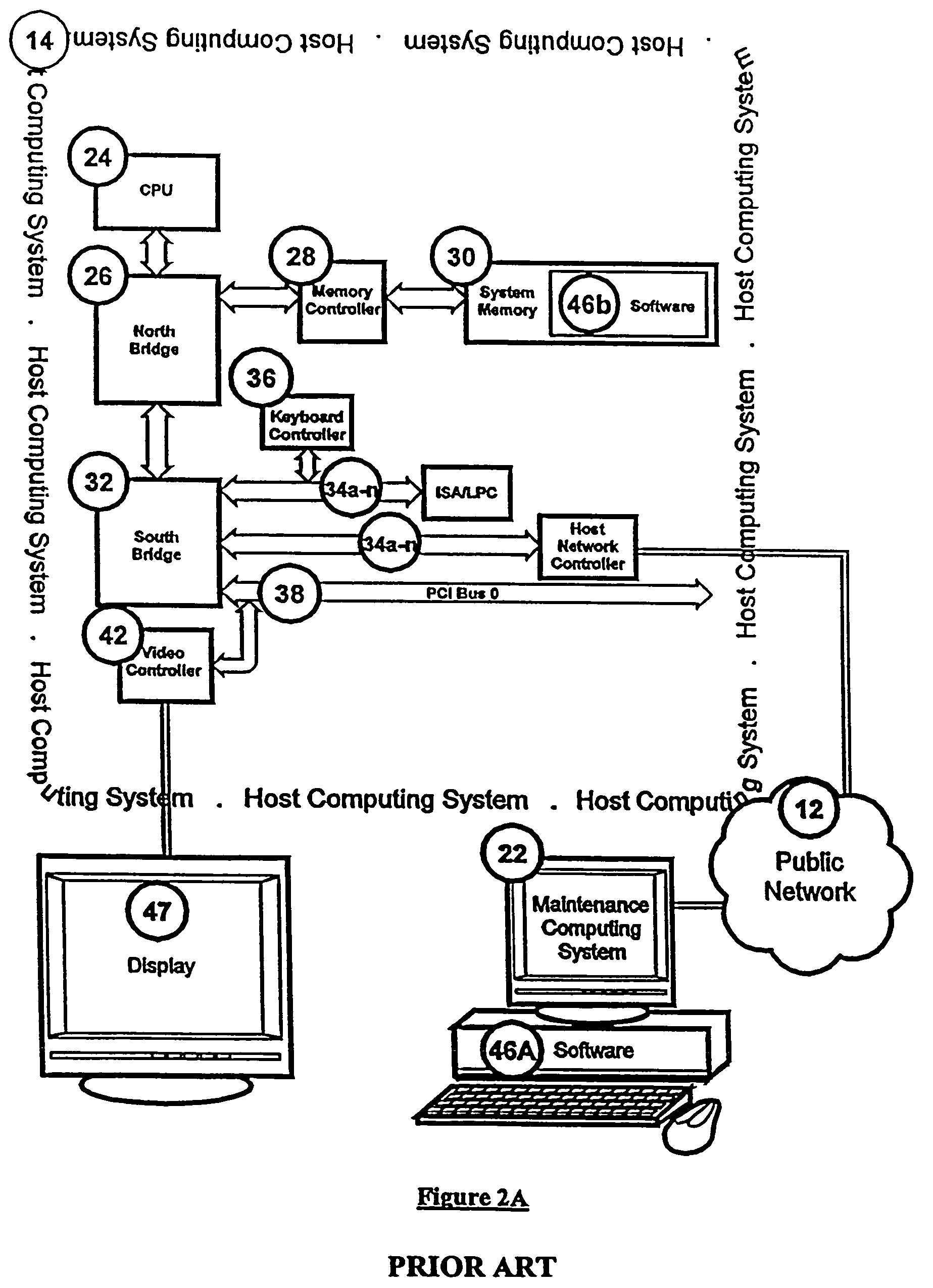
Another issue with conventional software-based maintenance systems is that the software, 46a and 46b; resident on the host and maintenance computing systems is OS-based software and are only operable once the operating system has been initialized.
As such, the software is not operable during power on and initialization of the host computing system.
Thus, the maintenance personnel located at the remote location cannot assess if there are problems with the host computing system that are found and flagged during POST.
However, if the snooping hardware determines that the video controller is in the graphics mode, such as after the operating system has started, then the graphics data location is unknown to the snooping hardware, as it varies from controller to controller.
Although the software / hardware hybrid system illustrated in FIG. 2B provides several advantages over the conventional software-based systems, there are also some disadvantages with these conventional systems.
In addition to the problems with software 46b, there are also problems concerning which PCI Bus the video controller is connected to in a given host computing system.
However, the snooping hardware 48 can only emulate keyboard and mouse commands if it is connected to PCI Bus 0.
Although these conventional systems reduce the amount of data that must be sent for each new set of captured date, there is one significant drawback with these systems.
Errors are introduced into the data both in transforming the data to analog data and in digitizing the data.
These errors may be somewhat random, such that two identical sets of analog screen data converted to digital format at different times may be completely different.
These errors may alter the display data such that more of the data seems to be different between different sets of captured data.
As such, the system may transmit data to the maintenance computing system, even when there has been no change in the display, thereby requiring huge amounts of data to be transmitted over the private network 50, making it a slow process.

Method used


Image

  • Systems and methods for capturing screen displays from a host computing system for display at a remote terminal
  • Systems and methods for capturing screen displays from a host computing system for display at a remote terminal
  • Systems and methods for capturing screen displays from a host computing system for display at a remote terminal

Examples


Embodiment Construction

[0045]The present invention now will be described more fully hereinafter with reference to the accompanying drawings, in which preferred embodiments of the invention are shown. This invention may, however, be embodied in many different forms and should not be construed as limited to the embodiments set forth herein; rather, these embodiments are provided so that this disclosure will be thorough and complete, and will fully convey the scope of the invention to those skilled in the art. Like numbers refer to like elements throughout.

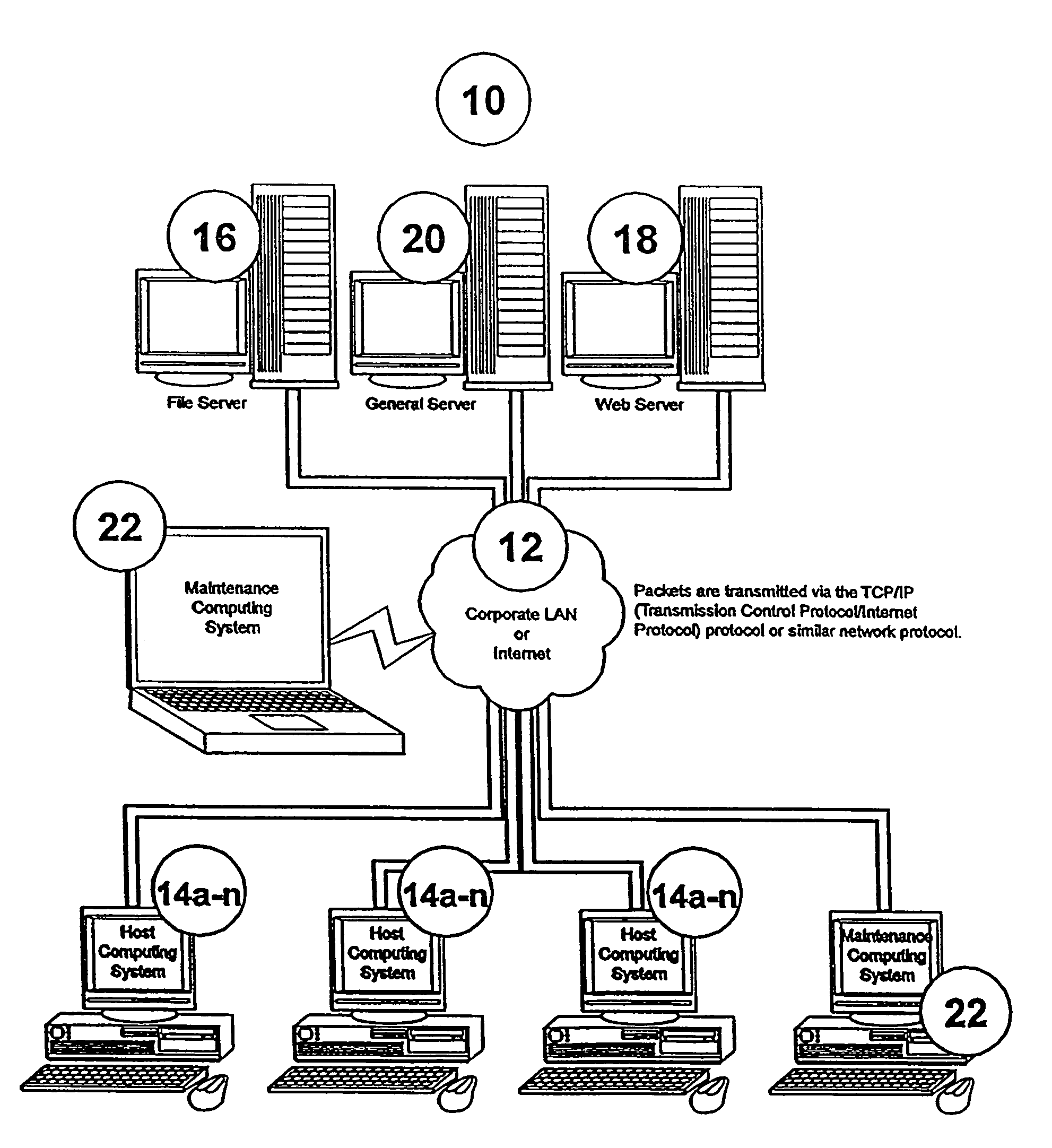
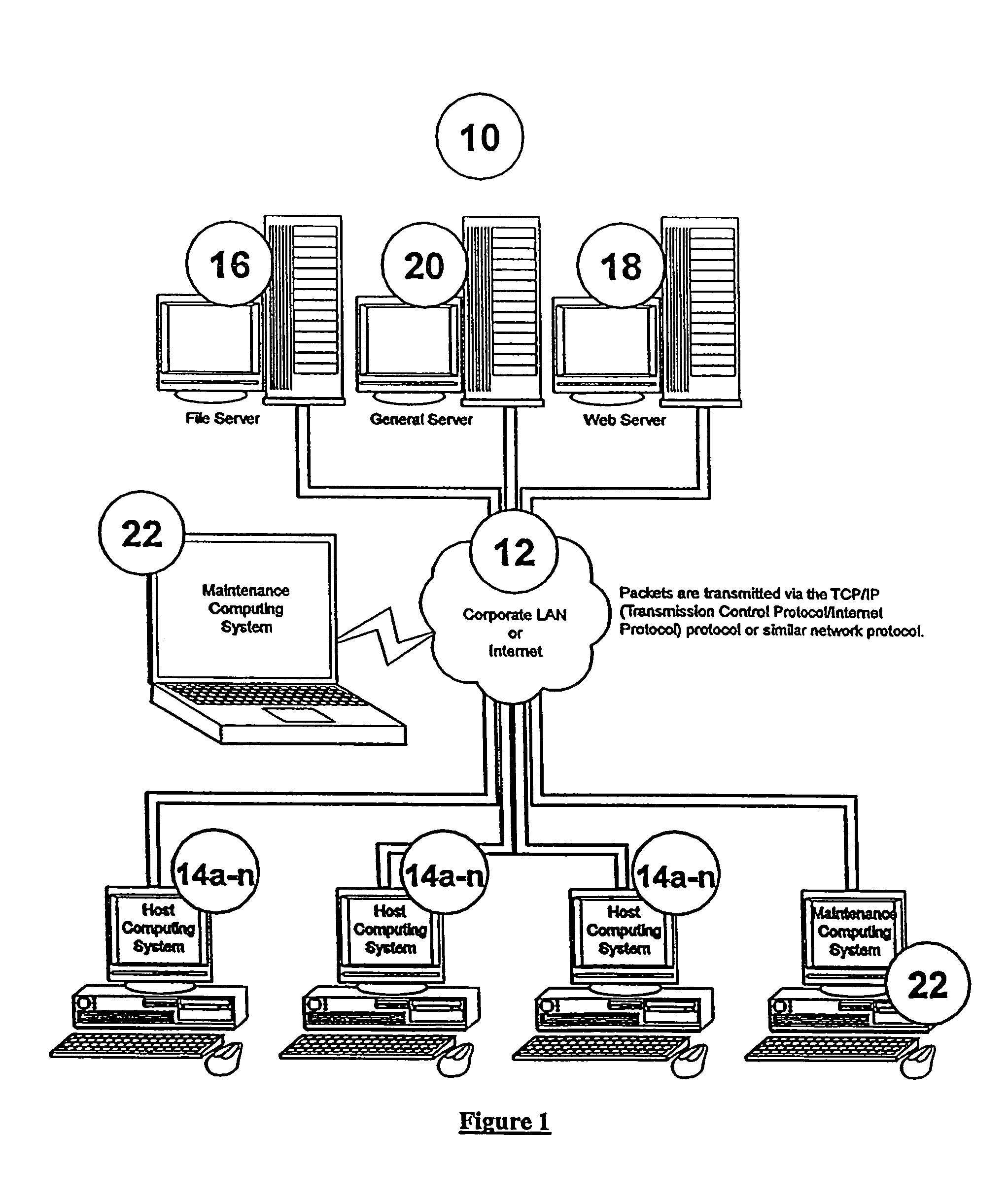
[0046]FIG. 3A illustrates a general embodiment of the present invention as illustrated in the network system 10. FIG. 3A illustrates a host computing system 14, network 12, and a maintenance computing system 22. These devices are all part of a larger network system, such as the system illustrated in FIG. 1. The host computing system 14 associated with the present invention is similar to those previously discussed. However, the host computing system include...


PUM


Abstract

The present invention provides systems and methods for monitoring a host computing system from a maintenance computing system located at a remote location. The system of the present invention includes a frame grabber that is connected the digital output of a video controller associated with the host computing system and collects sets of data output in digital form from the video controller independent of an analog to digital converter. Each collected digital data set represents a frame of data displayed on a terminal of the host computing system by the video controller and is stored in a storage device associated with the frame grabber. Successive sets of data are also compared to each other, and the differences between the data are also stored in the storage device. During a maintenance session, a first data set representing the data currently displayed on the terminal of the host computing system is transmitted to the maintenance computing system, and thereafter, only changes between successive data sets are transmitted to update the maintenance computing system.

Description

CROSS REFERENCE TO RELATED APPLICATION[0001]This application is a continuation of application Ser. No. 10 / 016,484 filed Dec. 10, 2001, which has issued as U.S. Pat. No. 6,825,846.FIELD OF THE INVENTION[0002]The present invention relates in general to systems and methods used for emulation on a remote terminal of information displayed on a host computing system, and more particularly to a terminal emulation system and method that uses a hardware interface with the host computing system for capture of displayed information, capture of information concerning host computing system health information, and control of keyboard, mouse, and drives of the host computing system.BACKGROUND OF THE INVENTION[0003]In recent years there has been a significant increase in reliance on computing systems to aid workers in performance of their assigned task. In fact, it is not uncommon for most, if not all, employees of a company or other organization to have access to some type of computing system. To ...

Claims


Application Information

Patent Timeline
Patent Type & Authority Patents(United States)
IPC IPC(8): G09G5/36G06F15/16G06F15/173G09G5/00H04L12/26H04L29/06H04L29/08
CPCH04L12/2602H04L29/06H04L43/00H04L67/08H04L69/329H04L9/40
Inventor MONDAL, UMASANKAR
Owner AMERICAN MEGATRENDS
Learn More