

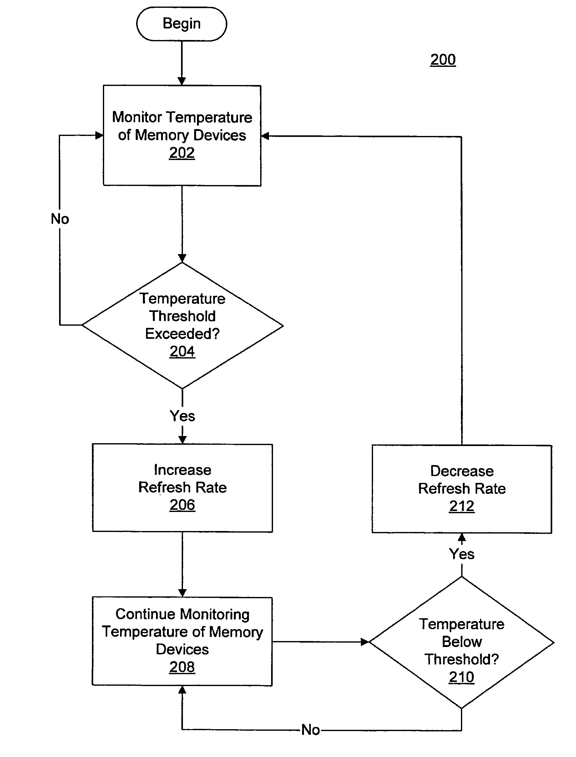
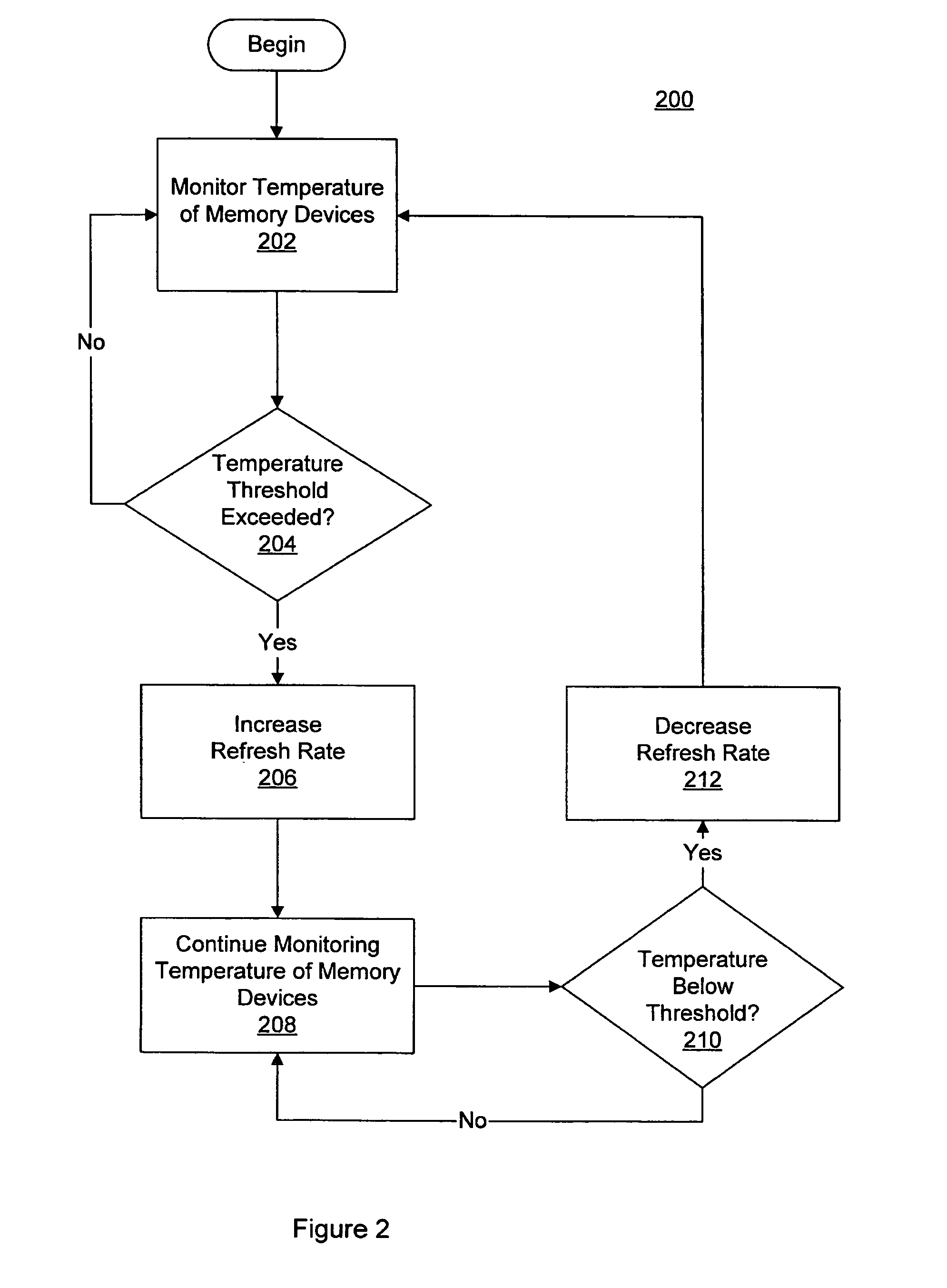
Variable memory refresh rate for DRAM
- Summary
- Abstract
- Description
- Claims
- Application Information
AI Technical Summary
Benefits of technology
Problems solved by technology
Method used
Image

Examples
Embodiment Construction
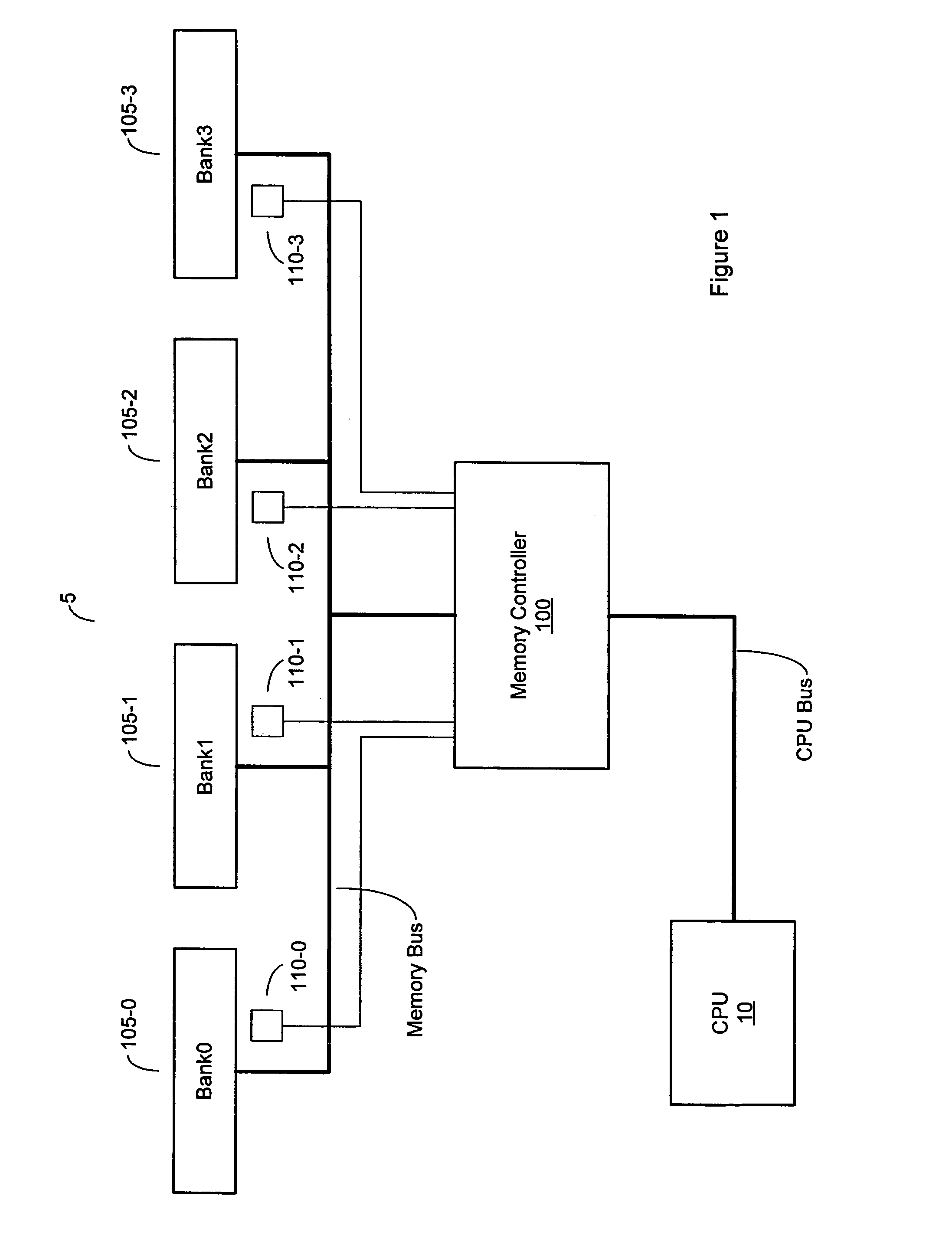
[0015]Turning now to FIG. 1, a block diagram of one embodiment of a computer system having a memory subsystem with a variable refresh rate is shown. In the embodiment shown, computer system 10 includes a central processing unit (CPU) 10 coupled to memory controller 100 via a CPU bus. In this particular embodiment, memory controller 100 is couple to, via a memory bus, four banks of memory, Bank0 through Bank3. These memory banks are implemented using memory modules 105-0 through 105-3, respectively. Embodiment having a greater or lesser number of memory banks are possible and contemplated, as well as memory banks having multiple memory modules. Each of the memory modules 105-0 through 105-3 may include one or more DRAM (dynamic random access memory) devices.
[0016]Memory controller 100 is configured to control accesses to each of the memory banks. This includes access to the memory banks for both read and write operations. Memory controller is also configured to initiate refresh cycle...
PUM
 Abstract
Description
Claims
Application Information