
Punch Press

a technology of motor-driven punch presses and punch presses, which is applied in the direction of press rams, forging presses, manufacturing tools, etc., can solve the problems of hindering the action of moment load, affecting the quality of machining, and affecting the effect of machining quality, so as to reduce noise, reduce the size of the drive transmitting mechanism, and the contact gear ratio is advantageously high.

Active Publication Date: 2007-06-26
MURATA MASCH LTD
View PDF10 Cites 10 Cited by
  • Summary
  • Abstract
  • Description
  • Claims
  • Application Information

AI Technical Summary

Benefits of technology

This configuration allows for controlled ram speed, reduced size, minimized vibration and noise, and improved machining accuracy by centralizing the servo motor and using helical gears to absorb axis shifts, enhancing the overall efficiency and reliability of the punch press.

Problems solved by technology

This hinders machining quality from being degraded by thermal deformation.
Further, driving is transmitted from both sides, thus hindering the action of a moment load and the like.

Method used


Image

  • Punch Press
  • Punch Press
  • Punch Press

Examples


Embodiment Construction

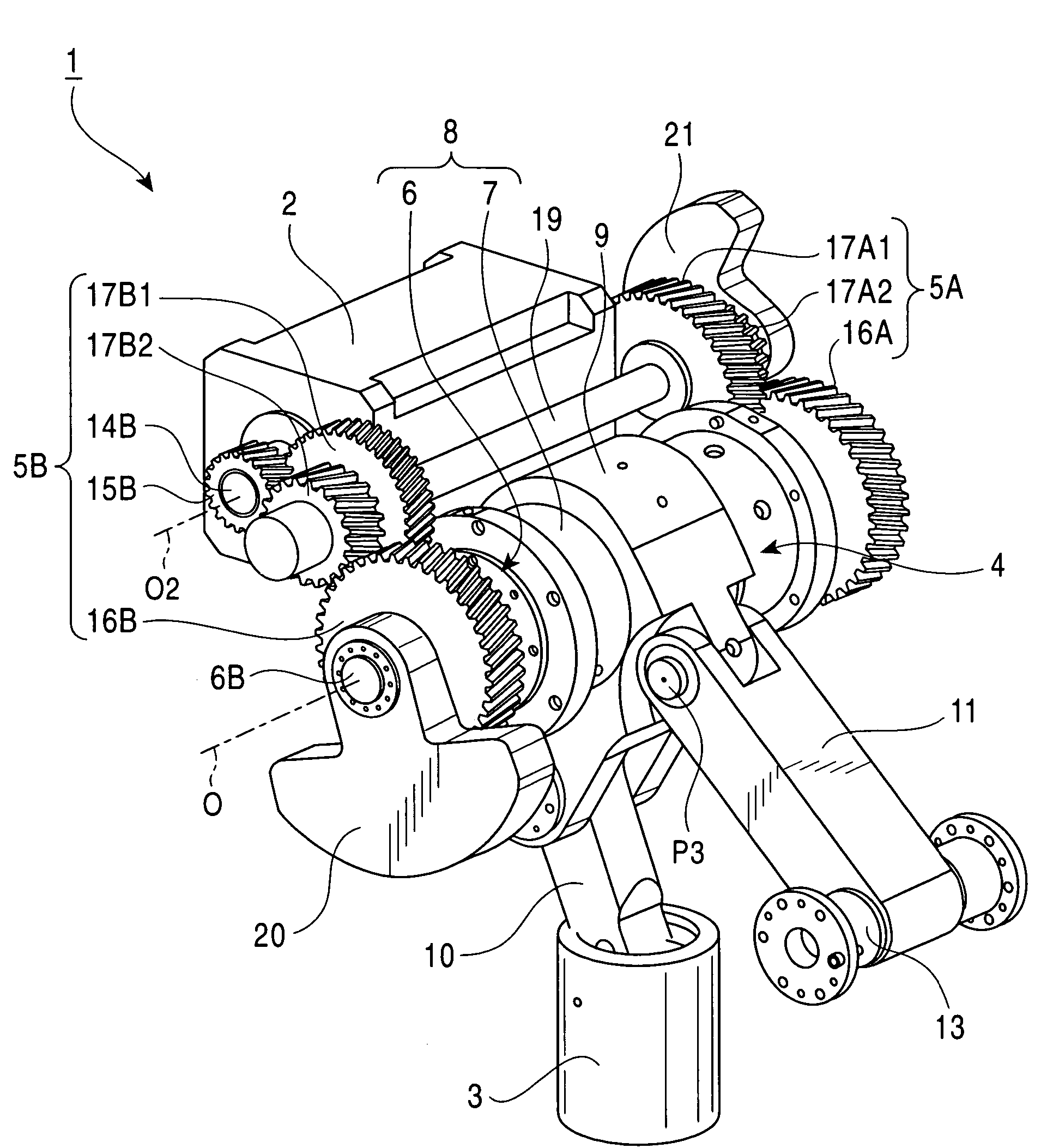
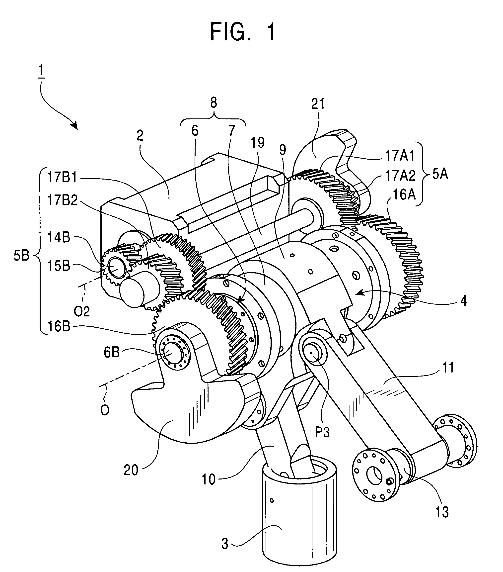
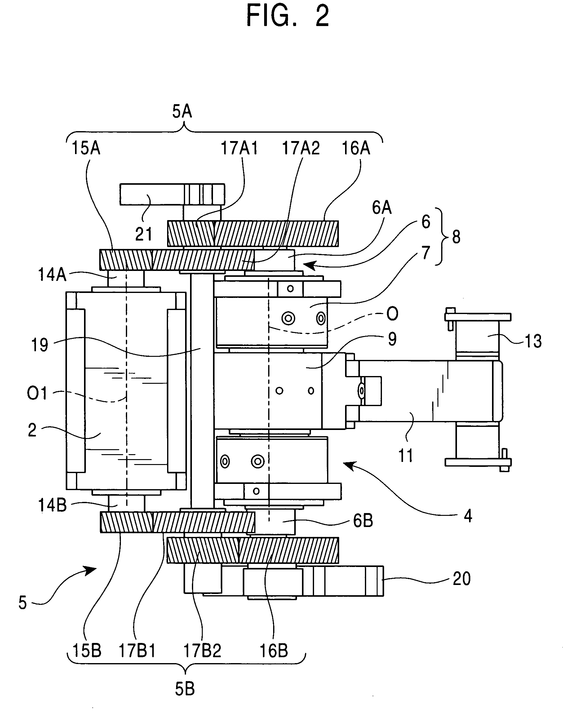
[0036]An embodiment of the present invention will be described with reference to FIGS. 1 to 6. FIG. 1 is a perspective view of a punch driving section in a punch press. The punch driving section 1 comprises a servo motor 2, a ram 3 which is installed so as to freely elevate and lower and which drives a press tool, a crank mechanism 4 that converts a rotating motion transmitted to a crank shaft 6 into an elevating and lowering operation of the ram 3, and a drive transmitting mechanism 5 provided between the servo motor 2 and the crank shaft 6. The drive transmitting mechanism 5 transmits rotation of the servo motor 2 to the crank shaft 6 while reducing the rotation speed so that the elevating and lowering operation of the ram 3 can be controlled by controlling the rotation of the servo motor 2. As shown in FIG. 4, the crank mechanism 4 has a crank member 8 having an eccentric shaft portion 7 eccentric to the axis of the crank shaft 6, a pivoting link 9 connected to the eccentric shaf...


PUM

PropertyMeasurementUnit
crank angleaaaaaaaaaa
rotation speedaaaaaaaaaa
rotationaaaaaaaaaa

Abstract

A punch press that provides an arrangement of a motor and a crank mechanism so that the motor does not project far from the side of a frame. The punch press includes a servo motor, a ram which drives a press tool, a crank mechanism which converts a rotating motion transmitted to a crank shaft into an elevating and lowering operation of the ram, and a drive transmitting mechanism which transmits rotation of the servo motor to the crank shaft while reducing rotation speed. The servo motor is next to the crank mechanism and its rotating axis is parallel to the axis of the crank shaft. The drive transmitting mechanism includes servo motor side gears joined to respective output shafts of the servo motor. The servo motor side gears respectively engage, directly or via intermediate gears, with crank side gears joined to the crank shaft.

Description

FIELD OF THE INVENTION[0001]The present invention relates to a motor-driven punch press driven by a servo motor or the like.BACKGROUND OF THE INVENTION[0002]Mechanical punch presses generally employ a crank mechanism as a slide driving mechanism that converts a rotating operation of a motor into an elevating and lowering operation of a ram. In such a punch press, a flywheel is generally connected to a crank shaft so that rotation of the motor can be transmitted to a crank mechanism via the flywheel (for example, the Unexamined Japanese Patent Application Publication (Tokkai-Hei) No. 6-344059).[0003]In a recently proposed mechanical punch press, a rotating operation of a servo motor is converted into an elevating and lowering operation of the ram via the crank mechanism without the need for the flywheel. The use of servo motor driving makes it possible to control the speed at which the ram elevates and lowers during a stroke. For example, the punch tool can be made to operate quietly...

Claims


Application Information

Patent Timeline
Patent Type & Authority Patents(United States)
IPC IPC(8): B21J9/18B21D28/36B30B1/26
CPCB30B1/266B30B15/0064
Inventor NAGAE, MASAYUKI
Owner MURATA MASCH LTD
Learn More