
Method and system for inspecting flaws using ultrasound scan data

a technology of ultrasound scan data and inspection method, applied in the field of inspection systems, can solve problems such as pipeline integrity degradation, defects and anomalies in pipelines, flaws or defects and anomalies can appear on the surface of pipelines

Active Publication Date: 2007-06-26
GENERAL ELECTRIC CO
View PDF17 Cites 73 Cited by
  • Summary
  • Abstract
  • Description
  • Claims
  • Application Information

AI Technical Summary

Benefits of technology

This approach significantly reduces false positive rates, enhancing the accuracy and reliability of flaw detection, allowing for more efficient maintenance by effectively separating weld and noise signatures from actual flaw signatures, as demonstrated by a reduction in false call rates from 82% to 7% in experimental results.

Problems solved by technology

Underground and underwater (deep sea) pipelines typically carry enormous quantities of oil and gas products that are important to energy-related industries, often under high pressure and at extreme temperatures and at high flow rates.
Flaws in constituent pipes may cause pipeline integrity degradation as the pipeline infrastructure ages.
Corrosion of a pipeline can be caused by small spots of weakness, subsidence of the soil, local construction projects, seismic activity, weather, and simply wear and tear caused by normal use, and can lead to defects and anomalies in the pipeline.
Thus, flaws or defects and anomalies can appear in the surface of the pipeline in the form of corrosion, mechanical damage, fatigue, crack, stress, corrosion cracks, hydrogen induced cracks, or distortion due to dents or wrinkles.
Maintaining and protecting existing pipeline networks is proving to be a challenge.
These techniques also result in high incidence of false positives because weld signatures (reflections from the weld interfaces of the pipeline) have very similar characteristics as cracks and notches and generally any feature recognition algorithm employed to extract flaws in the pipeline cannot easily distinguish between flaw signatures and weld signatures, which results in a high incidence of false calls.

Method used


Image

  • Method and system for inspecting flaws using ultrasound scan data
  • Method and system for inspecting flaws using ultrasound scan data
  • Method and system for inspecting flaws using ultrasound scan data

Examples


Embodiment Construction

[0018]The various aspects of the present technique deal with identifying and tagging of ultrasound signals reflected from lamination-like structures on parts. Though the aspects have been described in relation to pipeline applications where the lamination-like structure being addressed is a weld interface, the techniques described herein are equally applicable in other environments, for example, identifying flaws in rail tracks or planar flaws in sheets, rolls or plates. Aspects of the present technique are particularly advantageous as they serve to identify and remove all weld reflections from weld interfaces without removing any flaw signatures. The flaw signatures considered for retention may be, for example, cracks, notches, crack-fields, and combinations thereof.

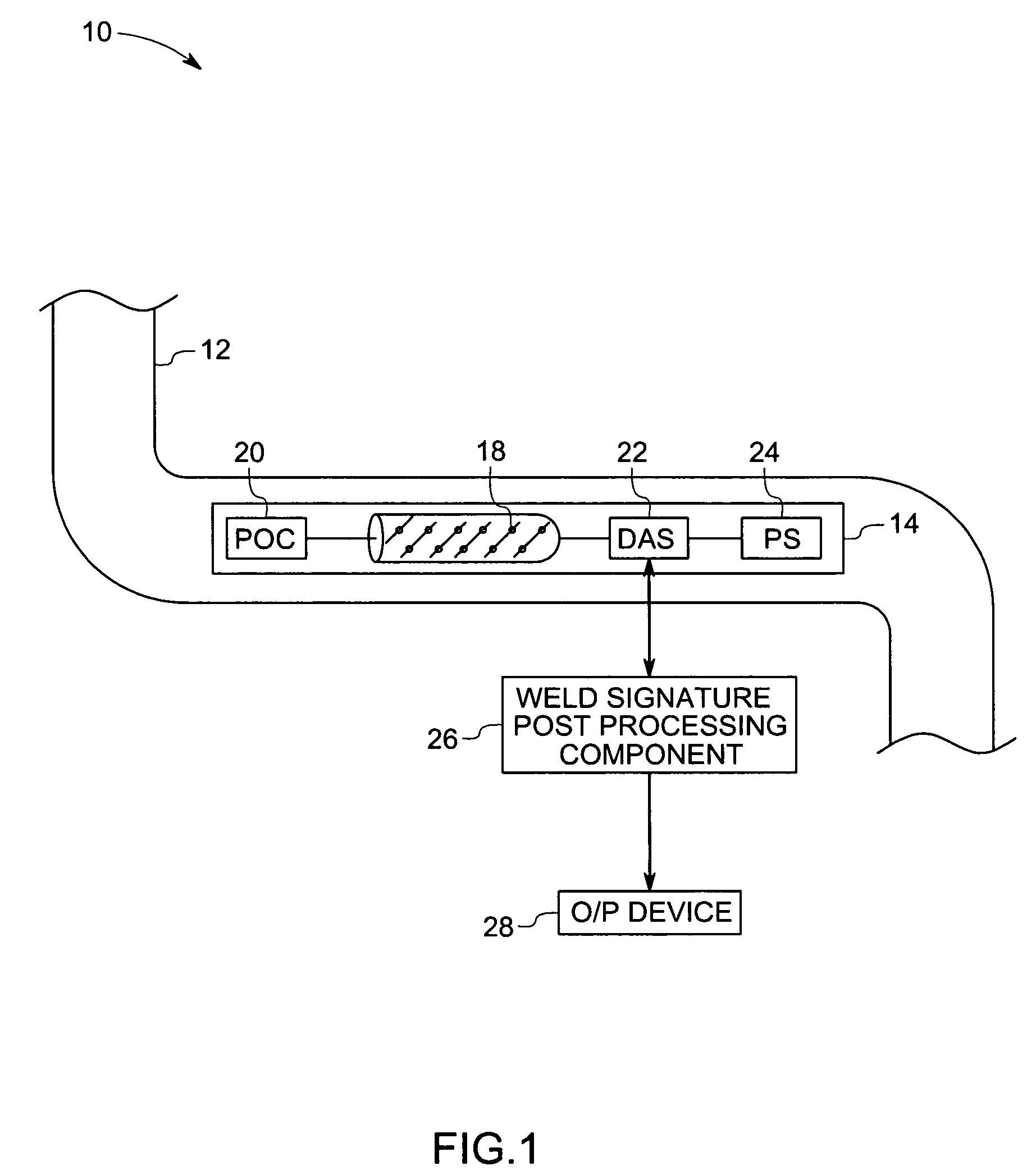
[0019]FIG. 1 is a diagrammatic representation of a pipeline inspection system, designated generally by reference numeral 10, that includes, a pipeline 12 and a pipeline inspection gage (PIG) 14. The PIG 14 is a scanning...


PUM

PropertyMeasurementUnit
anglesaaaaaaaaaa
ultrasound scanaaaaaaaaaa
weld angleaaaaaaaaaa

Abstract

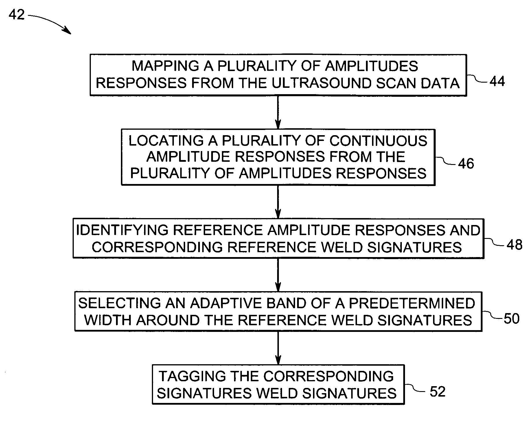
A method and system for detecting weld signatures from an ultrasound scan data obtained from scanning a pipeline is provided. The method includes a step for mapping multiple amplitude responses from the ultrasound scan data, each amplitude response being representative of a respective sensor signal. Continuous amplitude responses are located from the amplitude responses and corresponding signatures are identified for the continuous amplitude responses. The method also includes a step for tagging the corresponding signatures as weld signatures.

Description

BACKGROUND[0001]The invention relates generally to inspection systems and particularly to pipeline inspection systems that use ultrasound data for inspection of pipe flaws.[0002]Pipelines are widely used in a variety of industries, allowing a large amount of material to be transported from one place to another. A variety of fluids such as oil and / or gas are transported cheaply and efficiently using pipelines. Particulate matter, and other small solids suspended in fluids may also be transported through pipelines. Underground and underwater (deep sea) pipelines typically carry enormous quantities of oil and gas products that are important to energy-related industries, often under high pressure and at extreme temperatures and at high flow rates.[0003]Flaws in constituent pipes may cause pipeline integrity degradation as the pipeline infrastructure ages. Corrosion of a pipeline can be caused by small spots of weakness, subsidence of the soil, local construction projects, seismic activi...

Claims


Application Information

Patent Timeline
Patent Type & Authority Patents(United States)
IPC IPC(8): G01N29/06G01N29/40G01N29/48G01N29/11
CPCG01N29/11G01N2291/044G01N2291/105G01N2291/2675
Inventor DEWANGAN, SANDEEP KUMARSENGUPTA, ANANDRAJDUTTA, AMITABHA
Owner GENERAL ELECTRIC CO
Learn More