Slicer with unitary handle

a technology of a unitary handle and a slicer, which is applied in the direction of metal sawing devices, metal sawing apparatus, manufacturing tools, etc., can solve the problems of time-consuming cleaning of the handle and the tray, and achieve the effect of improving the strength of the attachment of the handle and being easy to clean

Inactive Publication Date: 2007-06-26
PREMARK FEG L L C
View PDF67 Cites 13 Cited by
  • Summary
  • Abstract
  • Description
  • Claims
  • Application Information

AI Technical Summary

Benefits of technology

[0004]The present invention is slicer having a tray with a unitary handle. In this manner, there are no crevices or voids between the body of the tra...

Problems solved by technology

In this case, food or other material may get trapped in the gaps ...

Method used


Image

  • Slicer with unitary handle
  • Slicer with unitary handle
  • Slicer with unitary handle

Examples


Embodiment Construction

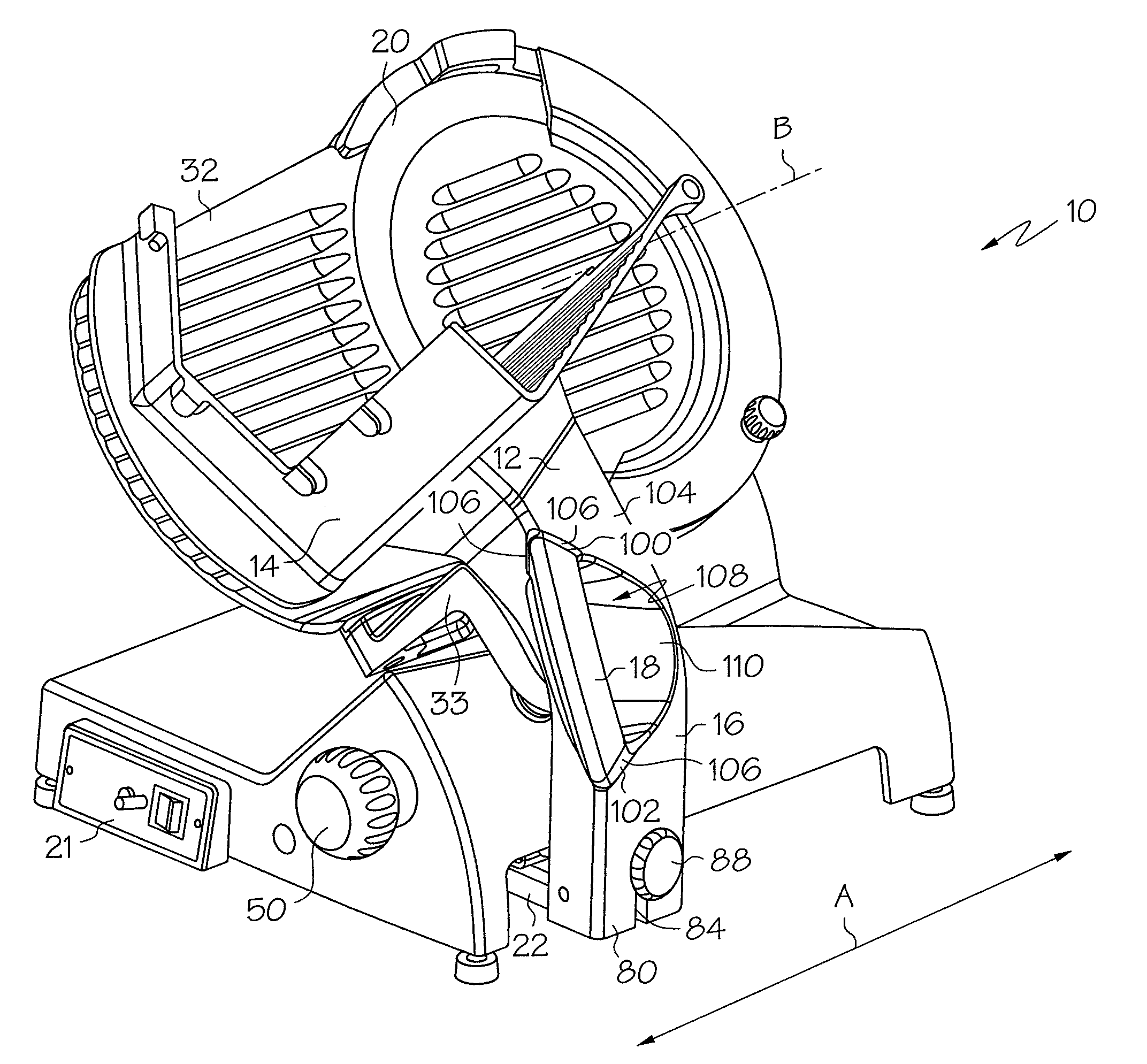
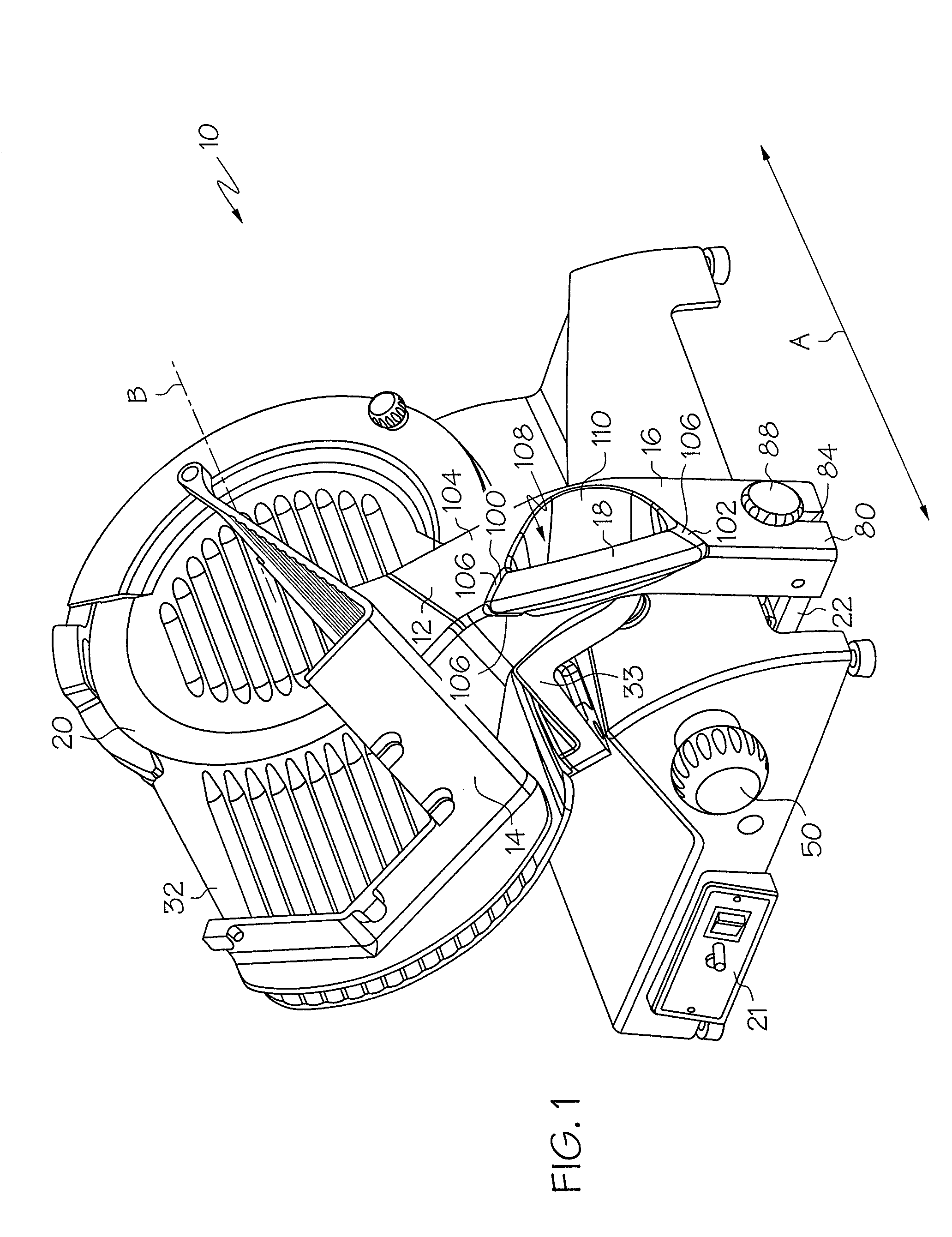
[0026]A slicer 10 having a tray 12 with a “V”-shaped plate or support surface 14 to receive and a support the food product to be sliced in shown in FIG. 1. The tray 12 includes a tray arm 16, and the tray 12 is typically powered along the slicing path A by a motor (not shown). Alternately, a user may grip the handle 18 and manually move the tray arm 16 along the slicing path A. The slicer 10 also includes a rotating, circular blade 20 having a central axis B. As the tray 12 reciprocates along the slicing path A, the tray 12 brings the food product into contact with the blade 20 to cut a slice off of the food product.

[0027]The tray arm 16 is coupled to a carriage 22 that extends below the body of the slicer 10 and includes an upwardly-extending end plate 24 (See FIGS. 3–4). The carriage 22 can be driven along the slicing path A and thereby drives the tray arm 16 along the slicing path A. During operation of the slicer, the tray 12 and carriage 22 preferably begin a slicing stroke at ...


PUM

PropertyMeasurementUnit
Shapeaaaaaaaaaa
Areaaaaaaaaaaa

Abstract

A slicer comprising a slicer body including a rotatable blade for slicing a product, and a tray mounted for reciprocal movement relative the slicer body and for supporting and moving the product relative the blade. The tray includes a tray body and a unitary handle. In another embodiment, the invention is a slicer including a slicer body having a rotatable blade for slicing a product and a tray for supporting the product and moving the product relative the blade. The slicer further includes a handle unitary with the tray, the handle providing a surface which a user may grip to manually move the tray.

Description

TECHNICAL FIELD[0001]The present invention is directed to a food slicer having a unitary handle.BACKGROUND OF THE INVENTION[0002]Commercial food product slicers are widely utilized as rapid and effective means for slicing meat, cheese, vegetables and other food products. Such a slicer is shown in U.S. application Ser. No. 09 / 470,351, filed Dec. 22, 1999, the contents of which are hereby incorporated by reference. The slicers commonly include a rotatable, disc-like blade, and a reciprocating tray that brings the food product into contact with the rotating blade to cut a slice from the food product. The tray may be motor or manually driven, and typically includes a handle that provides a surface that can be gripped by a user to manually move the tray. It is often desired to remove the tray from the slicer body to clean food, fat, or other debris off of the tray. Once the tray is removed from the slicer, it is typically carried to a sink for rinsing and cleaning.[0003]In most prior art...

Claims


Application Information

Patent Timeline
IPC IPC(8): B26D7/06B26D1/143B26D7/00B26D7/01B26D7/22
CPCB26D7/00B26D7/0616B26D1/143B26D7/01B26D7/22B26D2210/02Y10S83/932Y10T83/2048Y10T83/5833Y10T83/6499Y10T83/6534Y10T83/6536
Inventor ZHU, GUANGSHAN
Owner PREMARK FEG L L C
Why Eureka
Try Eureka